Effect of temperature difference on pressure loss
District heating network, part 4: how the temperature difference affects the pressure loss in the network
Overview
This part examines the relationship between temperature spread and pressure loss in the network. What happens when the temperature spread is changed? What must be considered, and how must the pump be set correctly?
Starting situation: 20 Kelvin spread

In the previous part, the heat network was operated with a 20 Kelvin spread. The steady-state calculation produces a pressure loss at the index point of 1.145 bar. Pump sizing shows the steady-state curve with this pressure loss, and a suitable pump has been assigned accordingly.
Checking the simulation results
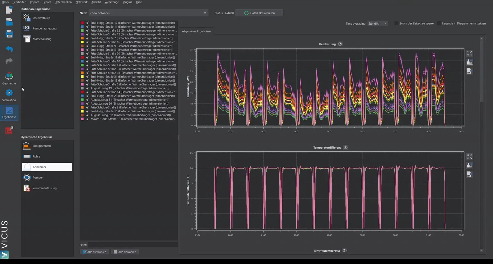
In the results under Consumers, it can be seen that the desired 20 Kelvin temperature difference is actually reached at every moment of heat extraction.
Changing the spread to 15 Kelvin
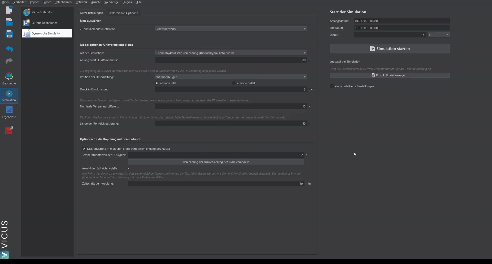
When changing the spread, two steps are necessary:
- In the steady-state calculation, set the spread to 15 Kelvin and recalculate. The pressure loss rises to 1.6 bar.
- In the systems, also set the control valve at the house transfer station to 15 Kelvin — this setting is configured there separately for the simulation.
Simulation with the wrong pump
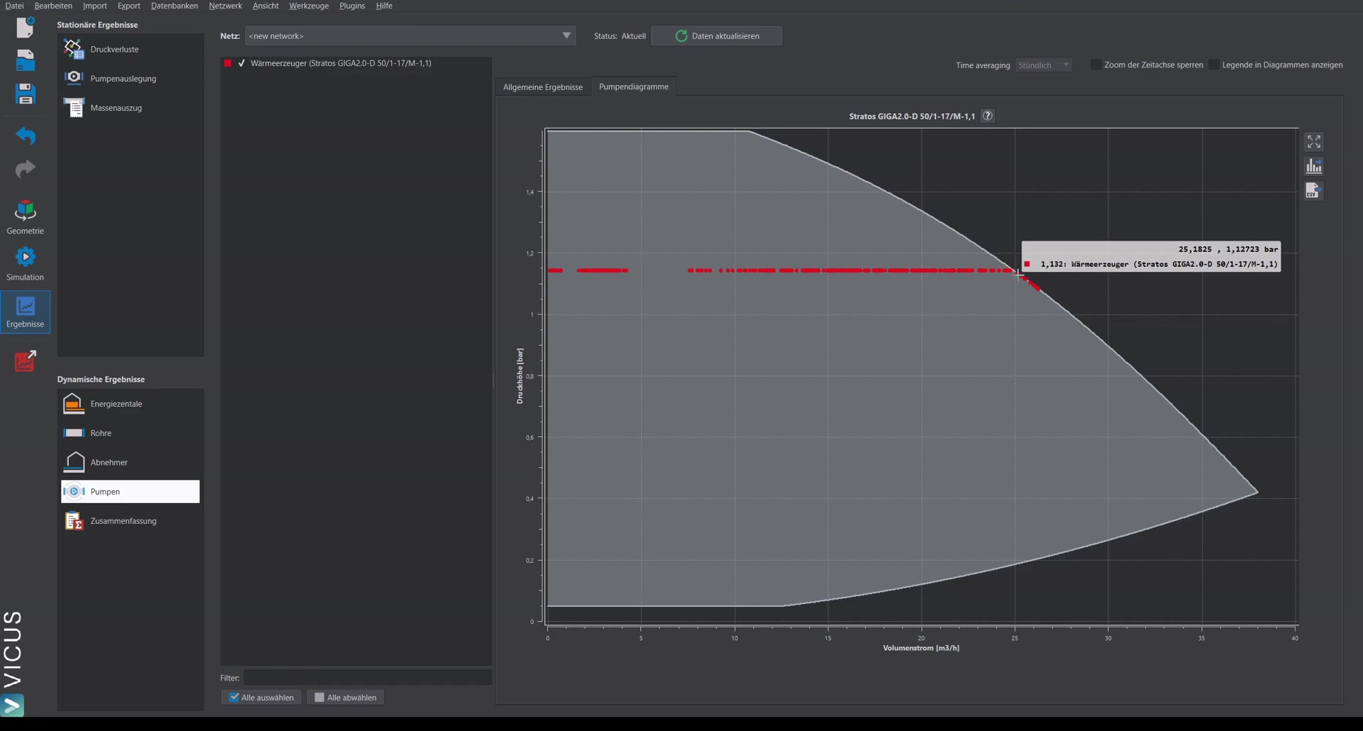
When simulating with the new spread but the old pump (sized for 1.1 bar), the problem becomes apparent: the spread is exceeded. The pressure difference has increased, but the pump is still set for the lower pressure difference. In the pump diagram, even the pump’s limit is reached — the curve bends off because the pump can no longer deliver more head.
Re-sizing the pump
To fix the problem:
- Switch to pump sizing again and refresh the steady-state calculation.
- Select a suitable pump from the database and assign it.
- The new pump now has the correct head of approximately 1.6 bar set.
Simulation with the correct pump
After restarting the simulation with the new pump, the 15 Kelvin temperature difference is correctly maintained again. In the pump diagram, all operating points move within the intended operating range.
Conclusion
When changing the temperature spread, you must always ensure that the pump is sized to match. A smaller spread leads to higher mass flows and therefore higher pressure losses in the network — the pump must provide correspondingly more head.
By the way
The friction pressure loss of the pipes grows quadratically with the mass flow. If you reduce the spread from 20 K to 15 K, the volume flow rises by about one third — so the pure pipe pressure loss rises by more than two thirds. That is why the pressure loss at the index point in the example climbs noticeably from around 1.1 to 1.6 bar. A large spread keeps pipes and pump small; but it must also be hydraulically achievable at every transfer station.