Importing DXF
Import DXF drawings as a site plan, position them and convert DXF layers into pipes
Overview
VICUS Districts imports DXF drawings (e.g. site plans, cadastral extracts, existing-condition plans from CAD programs) as a background drawing. The drawing serves as a reference for route planning; in addition, individual DXF layers can be converted directly into pipes of the network.
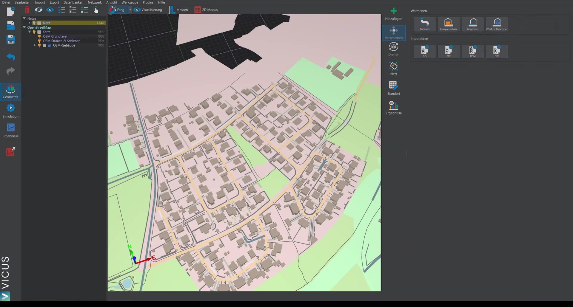
Opening
- Menu Import > DXF file …
- alternatively the button
 DXF in the Import section of the Add geometry panel
Import dialog
| Option | Default | Meaning |
|---|---|---|
| Name | File name | Display name of the drawing in the navigation tree. |
| Unit of measurement | Auto | Unit of the drawing coordinates: Auto, Meter, Decimeter, Centimeter or Millimeter. With Auto, the unit is determined automatically. |
Via show detailed settings, further options are available:
| Option | Meaning |
|---|---|
| Import text (experimental) | Takes over text elements (labels) from the DXF file. |
| Define a custom center point | x/y coordinate that is used as the center point of the drawing. |
| Move drawing to center point | Moves the drawing to the coordinate origin during import – helpful for drawings with very large coordinate values (e.g. state coordinates). |
Note on the unit of measurement
Leave the setting on Auto at first. In DXF files, the unit of measurement is often not stored (correctly) and therefore has to be determined automatically. If the scaling factor specified in the file header differs from the automatically determined one, VICUS Districts asks which one should be used. If the drawing appears clearly too small or too large after import, import it again with a different unit of measurement.
Practical tip
The quickest way to check the scale is against a known distance: measure a real building or property edge in the imported plan and compare it with the actual dimension. A common mistake is plans in millimeters instead of meters – the drawing then appears too large by a factor of 1000. If the scale is wrong, importing again with the correct unit of measurement is usually faster than scaling afterwards.
Editing the drawing
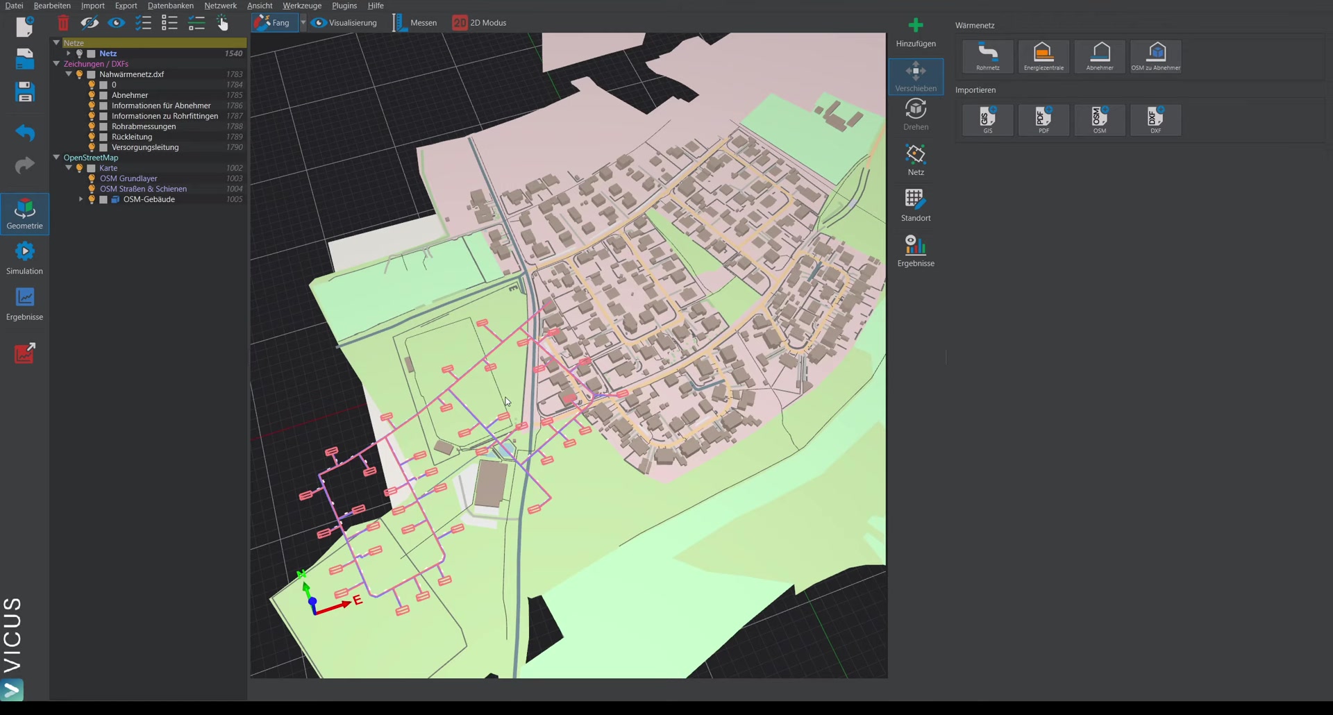
The imported drawing appears in the navigation tree with all layers of the DXF file:
- Visibility: Show and hide the entire drawing or individual layers via the visibility icons.
- Display: Double-clicking the drawing in the navigation tree opens the settings for text size and line width.
Moving the drawing
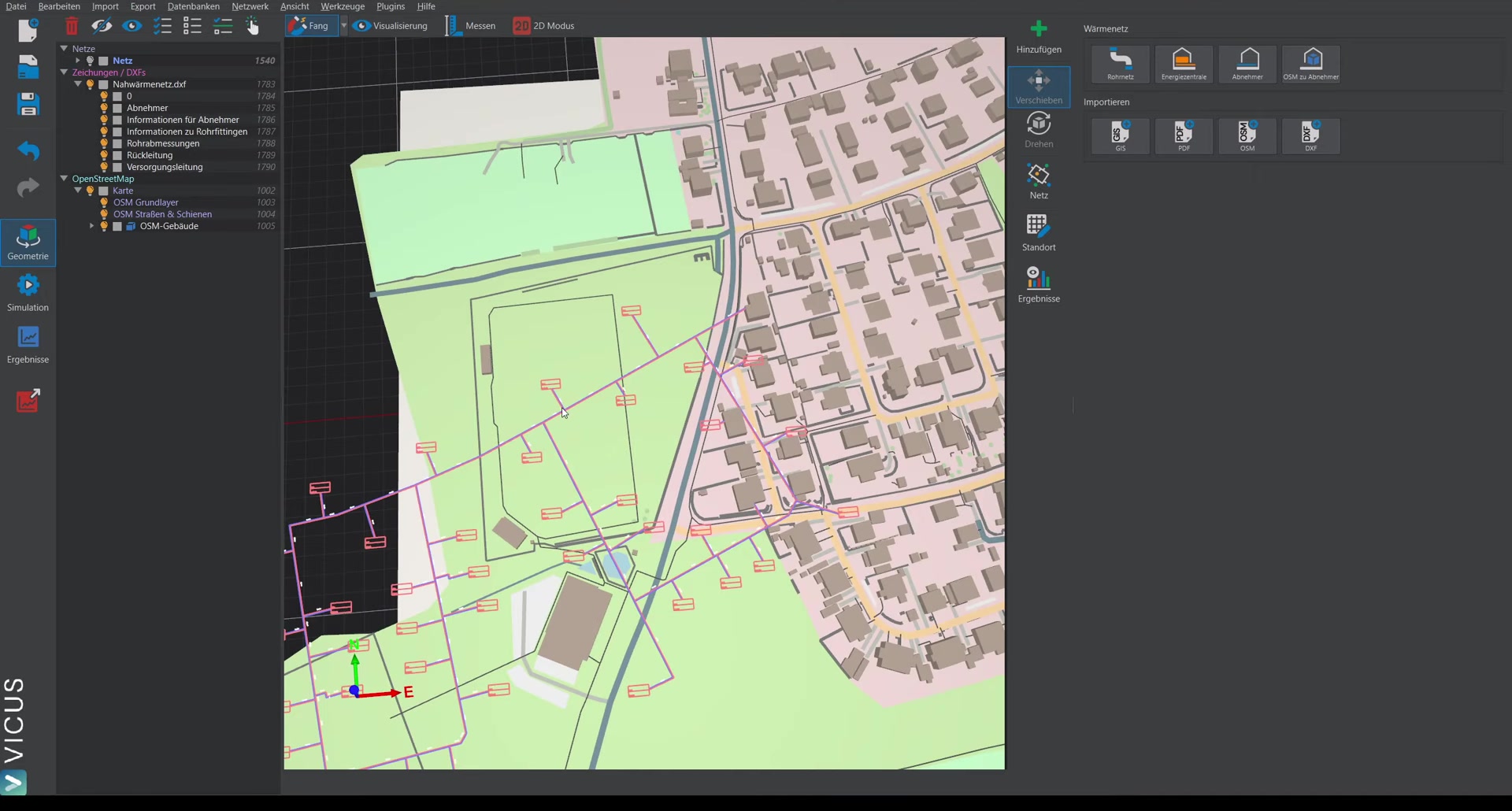
- Select the drawing (in the view or in the navigation tree).
- Switch to move mode.
- Drag the yellow sphere to the desired position.
For very large drawings, the move point can be hard to find. In that case, first place the local coordinate system at a suitable spot on the drawing and move precisely from there. After positioning, cancel the selection with ESC.
Converting DXF layers into pipes
If the DXF file already contains a drawn network route (e.g. from a preliminary design), the pipes do not have to be redrawn:
- In the Add geometry panel, switch to the
 Layer to pipe mode (convert DXF layer into pipe).
 - Select the DXF layer with the route layout.
- The polylines of the layer are taken over as routes (edges) into the active network.
The generated routes can then be edited as usual, connected with consumers and sized.