Steady-state calculation & pump sizing
District heating network, part 2: perform the steady-state calculation and size the pump
Overview
This part demonstrates how to edit the system configuration, perform a steady-state calculation, and size the pump. The starting point is the network created in the first part.
Checking the system configuration
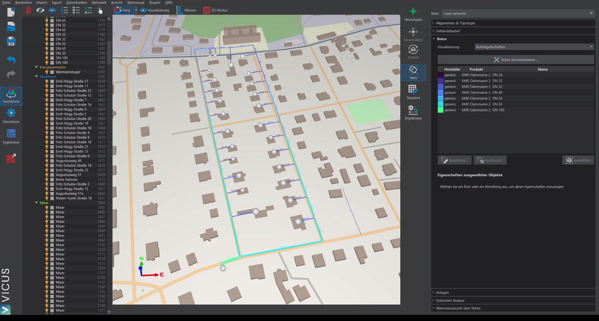
In the Systems view, it is shown which systems are assigned at which point.
House transfer station
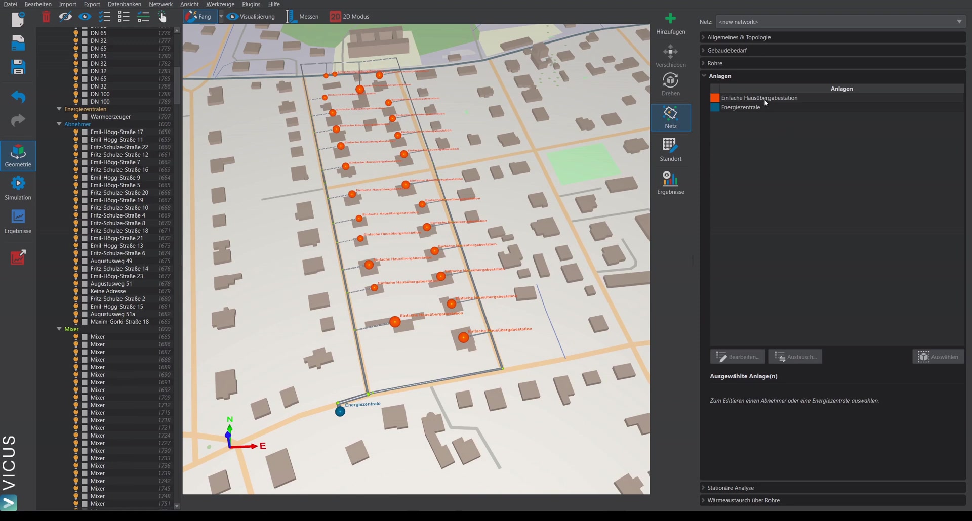
Double-clicking the entry opens the plant editor. The simple house transfer station contains:
- A heat exchanger with a pressure loss of 0.5 bar
- A valve that regulates a temperature difference of 20 Kelvin across the heat exchanger
Energy plant
The energy plant contains:
- A circulation pump with an initially constant pressure increase of 2 bar (it will be sized afterwards)
- A simple heat generator with a constant supply temperature of 80 °C
Performing the steady-state calculation
- Switch to the Steady-state analysis tab.
- Open the dialog — here you can configure supply temperature, temperature difference, setpoint of pressure maintenance, and the simultaneity.
- Create the steady-state calculation.
Results of the steady-state calculation
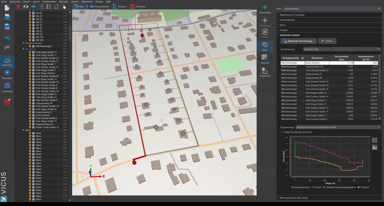
The results show:
- The pressure loss at the index point and the critical path displayed in color
- By selecting different entries in the table, the pressure losses at each consumer can be displayed
- The pressure profile along the branch, optionally with or without geodetic height
- The pressure exceedance and further pressure quantities at the individual points of the network
Below the path profile there is additionally a status line that checks the pressure course against two limits: the Highest operating pressure against the nominal pressure rating of the pipes on the path, and the Lowest operating pressure against the min. operating pressure. It reports All pressure limits are complied with. or Not all pressure limits are complied with. and names the value, the limit and the deviation behind it. The same check is recorded as a table by the network report.
Important in practice
In the pressure profile, check not only the index point but also the operating pressure at the highest and lowest terrain points. Especially in hilly terrain, the geodetic height determines the required pressure maintenance. Why there is an upper and a lower limit at all is explained under meeting operating pressure limits in heat networks; the verdict on both limits is given in the status line below the path profile and in the network report.
Additional display options
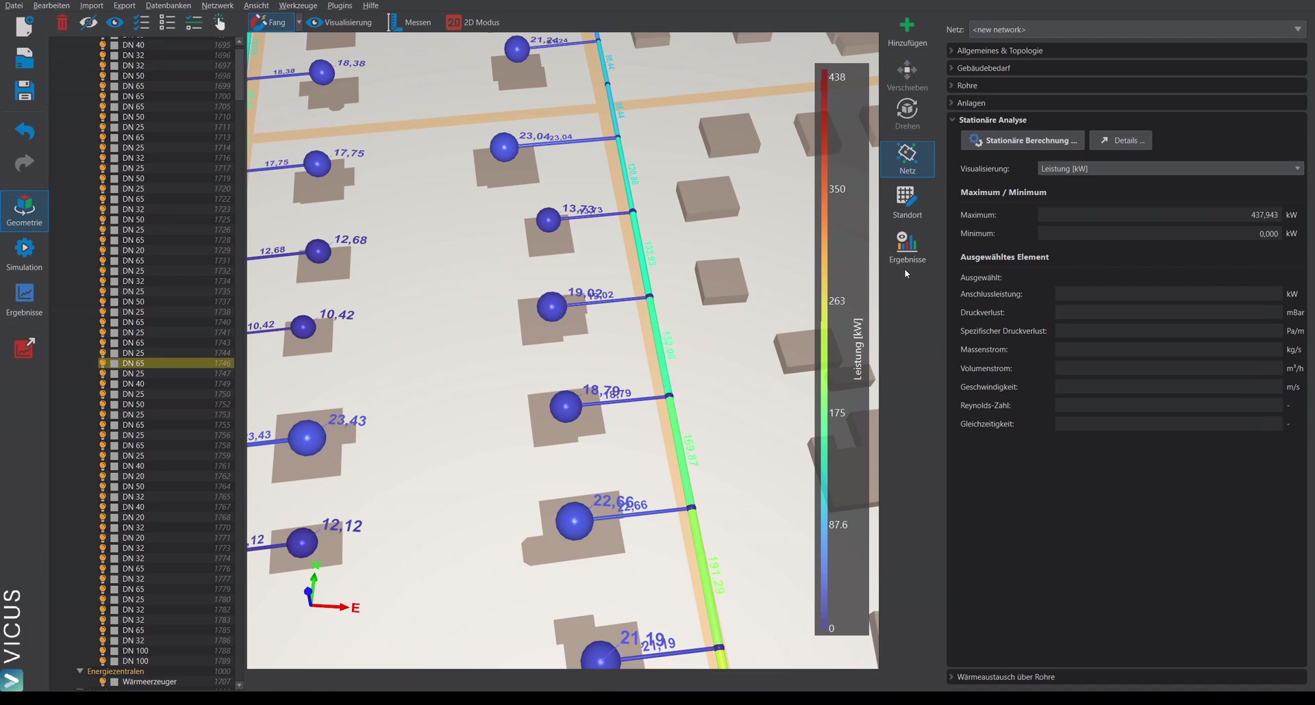
Additional quantities can be displayed in color in the network: specific pressure loss, mass flow, volume flow, and further results. Selecting an element shows additional results on the right side.
Detail results
Under Details you find a tabular overview of every component in the network — i.e. every component in the systems and in the pipe network, including pipe fittings, with the respective pressure loss, mass flow, volume flow, and operating pressure.
Sizing the pump
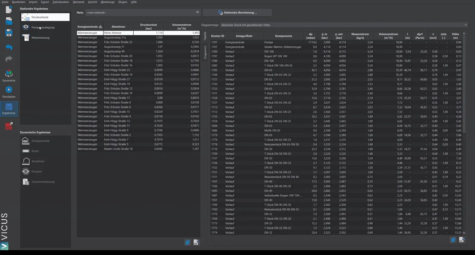
- Switch to Pump sizing.
- In the upper table the energy plant is displayed. Below it, suitable pumps are suggested.
- Select the desired pump and click Assign pump.
- The pump from the database is automatically stored in the system — the correct curves are assigned directly.
Verifying the pump in the system
Via Edit system and double-clicking the energy plant, you can verify that the correct pump curves are stored.