Drawing the network
Draw pipe routes, consumers and energy plants directly in the 3D scene - with snapping options and 2D mode
Overview
Heat networks can be drawn directly in the scene in VICUS Districts: pipe routes as polylines, consumers (transfer stations) and energy plants as individual points. Every click places a point, and snapping options ensure exact connections to existing nodes, pipes or imported drawings. Drawing by hand complements the import paths from DXF, GIS and OSM data, or fully replaces them for small networks.
How to open
The Add button in the left toolbar - opens the Add geometry panel. There, the Heat network group contains the drawing tools:
| Button | Function |
|---|---|
 Pipe network Pipe network | Draw a pipe route as a polyline |
 Consumer Consumer | Place consumers (transfer stations) as individual points |
 Energy plant Energy plant | Place an energy plant as a source node |
 OSM to consumer OSM to consumer | Convert imported OpenStreetMap buildings into consumers, see Importing OpenStreetMap |
Procedure
- Click a tool in the Heat network group - the property panel switches to drawing mode with the point list.
- Place points by clicking in the scene. All placed points appear in the point list of the panel; Delete last removes the most recently placed point. Alternatively, exact coordinates can be typed into the input line at the bottom edge of the scene and confirmed with Enter.
- Finish the point entry with the bold Create polyline button (for pipe routes) or Create points (for consumers and energy plants) - the panel switches to the property page.
- On the property page, choose the target network in the Network: field; the adjacent plus button lets you create a new network directly. The properties of the new objects are also defined here (see below).
- Apply with Create pipe network or Create consumer / Create energy plant - only then are the objects added to the project.
- Cancel or the ESC key discards the current entry and ends the drawing mode.
Options when drawing pipes
| Option | Default | Meaning |
|---|---|---|
| Pipe properties: | - | Pipe type from the pipe database that is assigned to the newly drawn routes (selection via the … button), see Pipe database |
| Automatically create intersections | enabled | Automatically creates nodes at crossings with existing pipes when finishing |
Options when placing consumers
For the consumer tool, the name (default: Single-family house) and the heat demand data are entered directly in the panel, including the Heating power in kW (default: 10 kW) and the resulting Connection load in kW. Details on the demand data: Consumers. Energy plants only require a name (default: Heat generator).
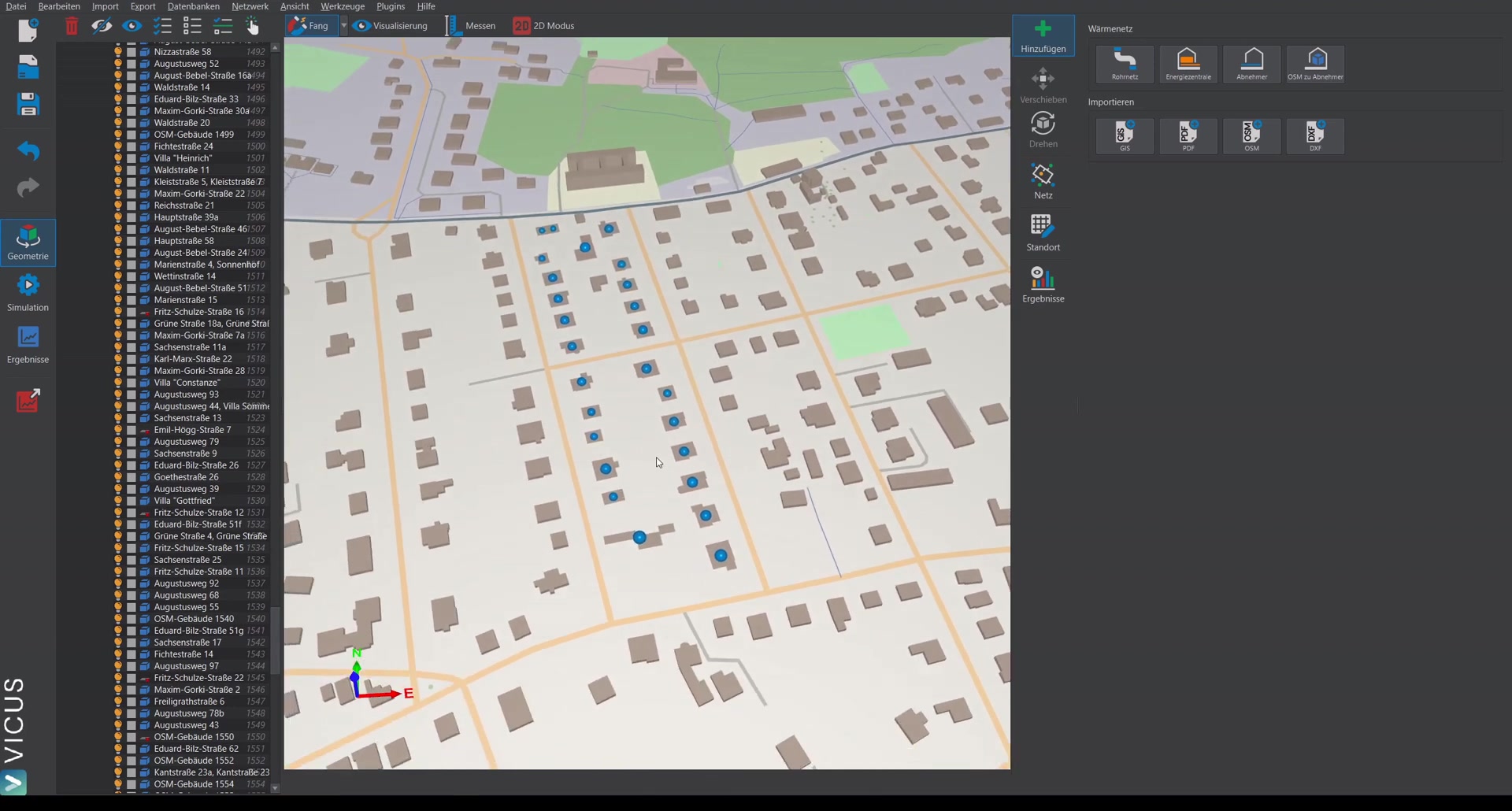
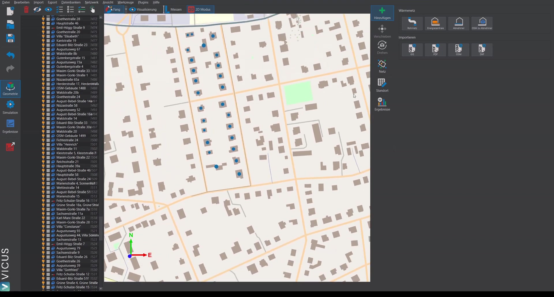
2D mode and snapping options
For drawing, the orthographic top view is recommended: the  2D mode button in the toolbar above the scene. This way all click points lie unambiguously in the plane and routes can be traced precisely over a site plan.
Object snapping is toggled on and off via the  Snap button or the F3 key. When snapping is active, an additional button opens the Snap options dialog, in which the snap targets are turned on and off group by group. While drawing, the local coordinate system jumps to the nearest enabled snap target within the snap distance - this produces exact connections without manual alignment.
| Group | Option | Snap to … |
|---|---|---|
| Grid | Grid plane | Raster of the grid plane |
| Network objects | Nodes | Existing network nodes - important for gap-free connections |
| Network objects | Edges | Existing pipe routes (edges of the network) |
| Drawings | Drawing points | Support points of imported DXF/GIS drawings |
| Drawings | Drawing intersections | Intersections of drawing lines |
| Drawings | Lines | Along the lines of a drawing (nearest point on the line) |
| Building objects | Corner points / Center points / Edge midpoints | Corner, surface or edge midpoints of existing component geometry |
| Miscellaneous | OSM buildings | Outlines of imported OpenStreetMap buildings |
| Miscellaneous | PDF / Bitmaps | Displayed PDF or image backgrounds |
| Miscellaneous | Soft axis lock | Softly locks onto an axis of the local coordinate system during interactive dragging |
The snap radius is set separately: the Distance: field (px) below the object groups applies to grid, network and building objects, a second Distance: field (px) below Drawings applies to drawing objects - each as a search radius in screen pixels.
For network drawing, the most relevant options are Nodes and Edges (gap-free connections to the existing network) as well as the Drawing and OSM options (tracing over an imported site plan).
Notes
- New points that lie closer than 0.1 m to an existing node are merged with it - no duplicate node is created.
- Whether the drawn network is fully connected is shown by the Network is connected: indicator on the Network tab, see Topology tools.
Practical tip
When tracing over an imported site plan, deliberately enable the Nodes and Edges snap targets and turn off distracting targets in the Snap options dialog. This way new routes connect gap-free to the existing network, instead of creating seemingly connected but hydraulically separate duplicate nodes. To check that everything hangs together in the end, use Network is connected: on the Network tab.