Object Tree
The object tree (navigation tree): toggling visibility and selection, locking and renaming objects, and editing drawings/DXF, layers and images.
Overview
The object tree – labelled navigation tree in the menu – on the left-hand side lists all objects of the project in a hierarchy: networks with their pipes and nodes, imported drawings and images, OpenStreetMap data and – when the building view is active – buildings and shading objects. Small icons in front of each entry control the visibility, selection and lock state of every individual object; a double-click renames objects or opens editing dialogs. Every change in the object tree can be reverted with Edit > Undo (Ctrl+Z).
Structure
The tree is organized by object groups. Each group only appears when the project contains the corresponding objects:
| Group (top-level node) | Child entries |
|---|---|
| Networks | for each network the categories Pipes, Energy centers, Consumers and Mixers with their individual objects |
| Drawings/DXFs | the layers of each drawing |
| Images | individual bitmap images |
| OpenStreetMap | Map with OSM Ground, OSM Streets & Railways and OSM Buildings |
| Buildings | Building → Levels → Rooms → Surfaces (only when the building view is active) |
| Shading objects | individual shading surfaces |
Notes on the structure:
- The active network is shown in bold.
- Group and category nodes (e.g. Networks or Pipes) cannot be selected and have no visibility icon – they only bundle the objects below them.
- Clicking the triangle in front of a node expands or collapses the branch; collapsing a branch also collapses all of its sub-branches. The expanded/collapsed state is preserved while editing.
- Surfaces with invalid geometry are shown in dark red; a tooltip states the cause.
- View > Show IDs in the navigation tree displays the numeric ID after each object name – helpful for matching against result quantities and messages.
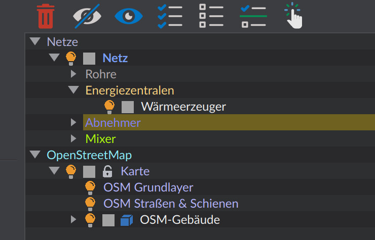
Icons in front of each entry
Depending on the object type, up to three clickable icons appear in front of an object’s name:
| Icon | Effect |
|---|---|
| Light bulb | Toggle the object’s visibility in the 3D scene |
| Selection box | Select or deselect the object |
| Lock | Lock/unlock the object (only for drawings, layers, images and the OSM map) |
A single click on an icon toggles the property for the object and all of its child objects. Hold Shift while clicking to apply the change only to the clicked object itself, without its child objects.
Visibility: showing and hiding
Hidden objects disappear from the 3D scene but remain in the project and in the object tree.
- Single object: click the light bulb in front of the entry.
- Several objects at once: first select them (see below), then use the object-tree toolbar:
 Hide selected objects (F6)
 Show selected objects (F7)
Hiding only affects the display; the objects are still exported and simulated.
Selection
Selected objects are highlighted in the 3D scene and form the basis for editing (moving, deleting, assigning properties). The selection in the object tree and in the 3D scene is synchronized.
- Single object: click the selection box in front of the entry (Shift = without child objects).
- Actions in the object-tree toolbar:
| Action | Icon | Shortcut |
|---|---|---|
| Select all |  | Ctrl+A |
| Deselect all |  | Esc |
| Invert selection |  | Ctrl+I |
| Smart select |  | Ctrl+F |
Smart select opens a dialog that lets you select or deselect objects specifically by their properties (object type, assigned components, etc.). Locked objects cannot be selected – their selection box has no effect.
Renaming objects
Many objects can be renamed directly in the tree:
- Double-click the object’s name – the name turns into an input field.
- Enter the new name and confirm with Enter.
Renaming is available for networks and network objects (pipes, energy centers, consumers, mixers), shading objects and – in the building view – buildings, levels, rooms and surfaces. Drawings, layers, images and OSM objects cannot be renamed; a double-click there opens the respective editing dialog instead (see below). An empty name is discarded, and duplicate names are made unique automatically. Renaming can be undone.
Locking objects
The lock icon protects objects from being moved or deleted by accident. It is only available for drawings, individual layers, images and the OSM map – typically for an imported site plan that serves as a drawing background.
A locked object:
- can no longer be selected and therefore not moved or deleted,
- but remains visible and continues to serve as a background for network planning.
Clicking the lock locks or unlocks the object together with its child objects (Shift = only the clicked object; the OSM map always includes its child objects).
Editing drawings and DXF
A double-click on the name of a drawing opens the Drawing properties dialog:
| Field | Meaning |
|---|---|
| Offset: (x, y, z) | Moves the entire drawing in space [m] |
| Scaling factor: | Unit of the source file (Meter, Decimeter, Centimeter, Millimeter) or Custom – converts the drawing to meters |
| Custom scaling factor: | Free conversion factor when Custom is selected |
| Line weight: | Scaling of the drawing’s line weights |
| Text size: | Scaling of the drawing’s text elements |
This lets you position an imported DXF site plan in the project and scale it to match the network. The individual layers of the drawing appear as child entries (see next section).
Drawing layers
Every imported drawing holds its layers as child entries in the object tree – just like the layers in a CAD program. Each layer offers the same icons as the drawing itself:
- Light bulb: show/hide individual layers to display only the relevant information of the site plan.
- Lock: lock individual layers against selection.
- Selection box: select the layer together with its drawing elements.
This way you can, for example, hide dimension or annotation layers and keep only route or building edges as a drawing background.
Editing images (bitmaps)
A double-click on an image opens a dialog to adjust its appearance:
| Field | Meaning |
|---|---|
| Brightness: | Brightness of the image |
| Saturation: | Color saturation of the image |
| Transparency: | Transparency, to display the image as a subtle background |
Images are used, for example, to place a scanned plan or an aerial photo as a background beneath the network.
Reassigning missing files
If a project references a drawing, image or OSM file that cannot be found, the entry appears as Missing or invalid file ’…’. A double-click opens a file dialog to reassign the file; the objects are then re-read automatically.
Removing objects
The button  Remove (Del) deletes the selected objects. If drawings or drawing layers are affected, a dialog asks for confirmation, because these objects often serve as a background. Removing can be undone.
Practical tip
Lock an imported site plan (DXF) with the lock icon right after importing it. It stays visible as a drawing background but can no longer be moved or deleted by accident while you draw the network on top of it. Hide any layers you do not need – such as dimensions or hatching – individually via the light bulb.