Simulate an active network with a central pump
Cold district heating, part 5: simulation of an active network with a central circulation pump
Overview
This part shows how a passive network with decentralized circulation pumps is converted into an active network with a central pump. The conversion is done in just a few steps.
Swapping the plants
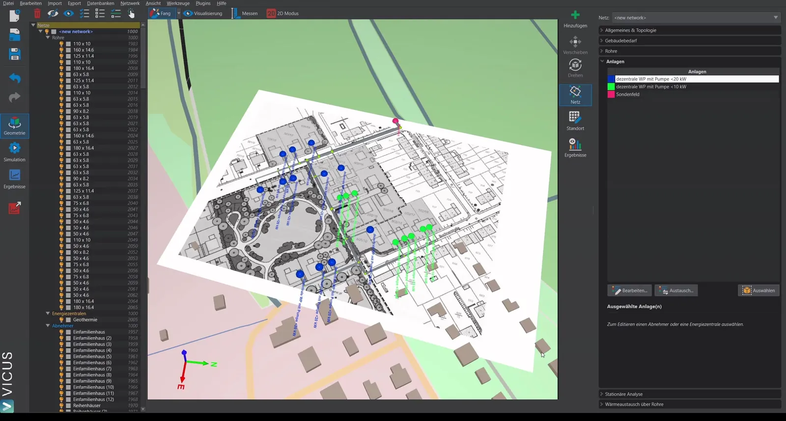
Starting from the previous example with decentralized heat pumps and circulation pumps:
- Select the decentralized heat pump with pump.
- Click Replace.
- Select a decentralized heat pump with valve from the database.
- Copy the element so that it can be edited.
- Repeat the procedure for all other plant types.
Structure of the new plant
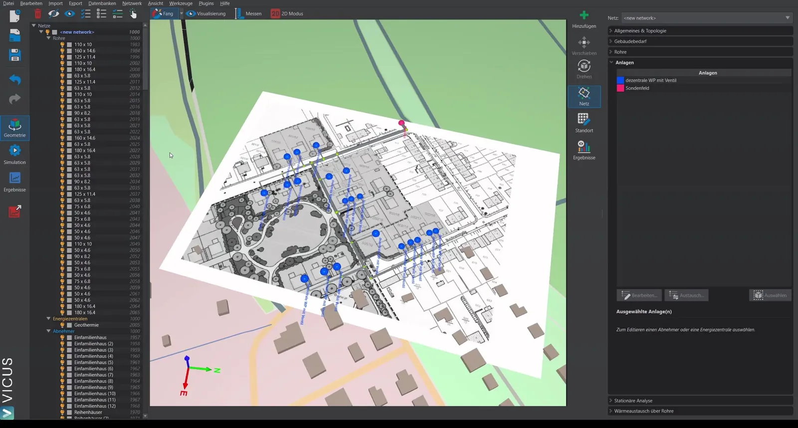
The new plant consists of:
- Heat pump with the corresponding pressure loss
- Valve (instead of the circulation pump), which regulates on a fixed temperature difference of 3 Kelvin
The consumer side is now passive — no decentralized pump is required any more.
Installing the central pump
The network still needs a circulation pump, which is now placed centrally in the borehole field:
- Open the borehole field in the plant editor.
- Delete the existing connection line.
- Drag a pump with defined head into the plant.
- Connect the elements.
- Confirm with OK.
The network has now been converted into an active system.
Performing the steady-state calculation
- Open the steady-state calculation dialog.
- For the supply, select a central pump instead of decentralized pumps.
- Start the calculation.
The pressure loss at the index point should hardly differ from the passive system, since only the pump has been swapped.
Pump sizing
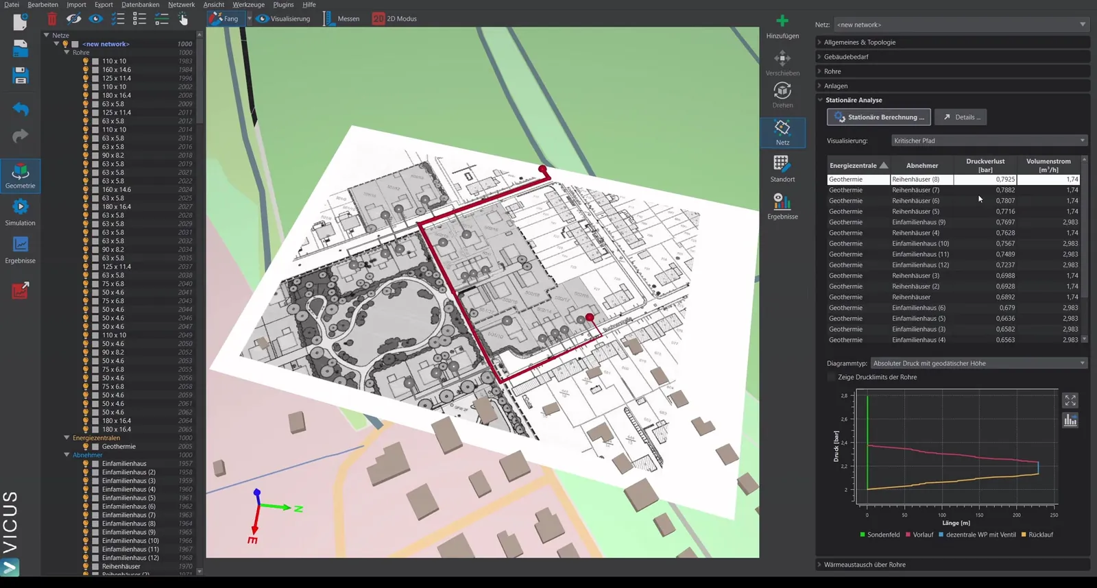
- Click Details > Pump sizing.
- The system curve is displayed.
- Select a suitable pump from the database.
- Click Assign pump.
The pump is stored in the plant with the corresponding curve and head.
Running the simulation
- Switch to the simulation.
- Set the simulation time (e.g. 14 days for a quick check).
- Start the simulation.
Evaluating the results
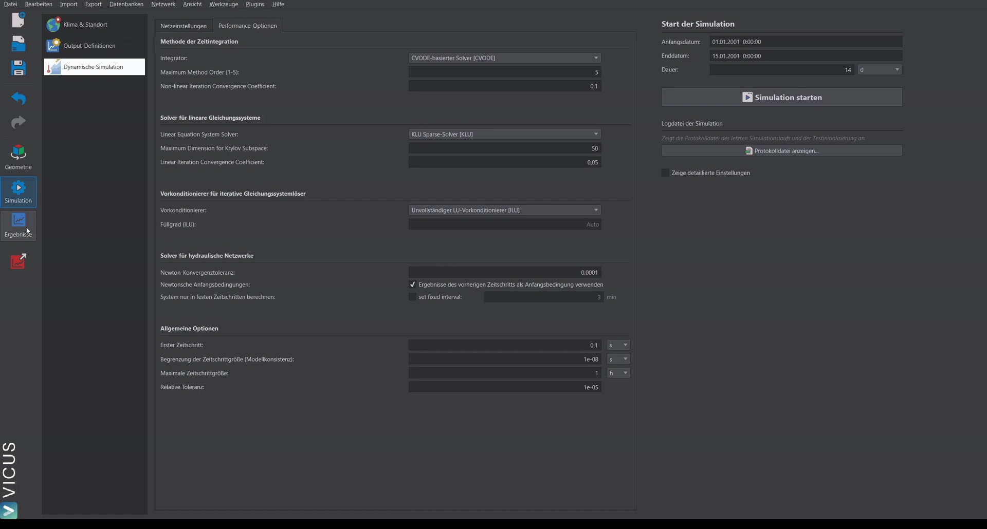
In results mode, check in particular:
- Temperature difference at the consumers: The configured 3 Kelvin should be reached. If not, the pump must be re-sized or the pressure increase adjusted.
- Pump diagram: The central pump runs with a constant pressure increase (e.g. 0.8 bar).
The system has now been successfully converted into an active network with a central pump.