Annual simulation & heat gains of the network
Cold district heating, part 4: perform the annual simulation and analyze the thermal gains of the network
Overview
This part shows how an annual simulation is performed to determine the heat gains of the pipe network. This is an essential aspect in the planning of cold district heating networks.
Checking the heat source
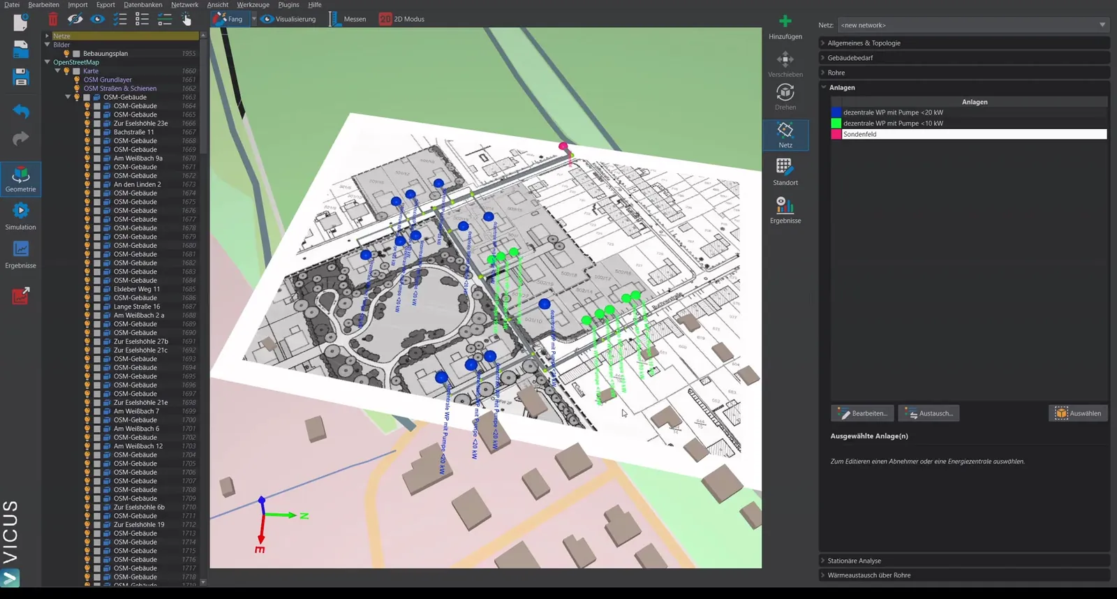
In the baseline example, a borehole field is placed as the heat source. The borehole field model accounts for:
- Hydraulic losses: Pressure losses of all parallel boreholes
- Heat exchange: A fixed time series for the borehole temperature
Adjusting the borehole temperature
If you simulate a cold district heating network with a borehole field, you can import the borehole temperature from your borehole sizing software. To do so, switch to user-defined temperature and select a corresponding TSV file.
Ground boundary conditions for the pipe network
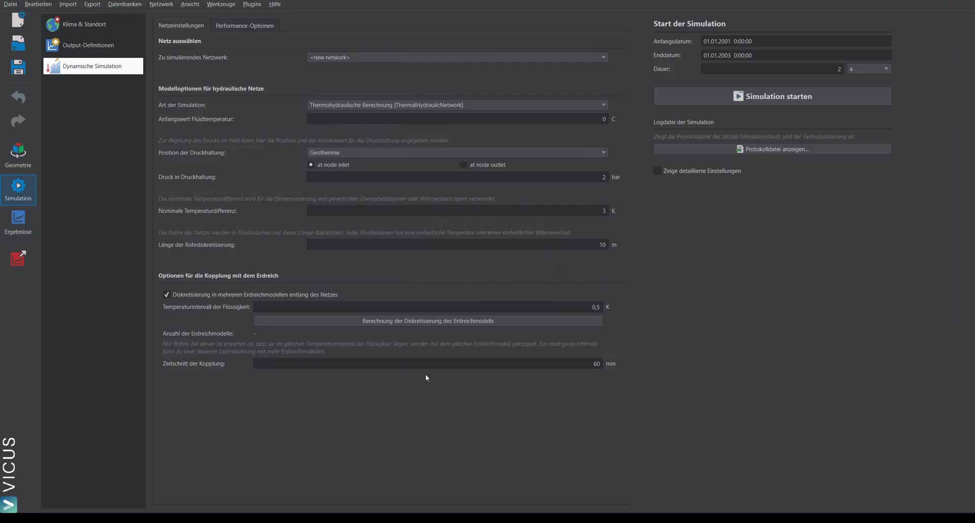
Under Heat exchange via the pipes, the ground boundary conditions can be configured:
- Set the soil type
- Define the burial depth and pipe spacing
- Enter the moisture content of the ground
- Account for ice formation — recommended for simulations with a borehole field or collector field in order to capture the full ground heat gains
Alternatively, a fixed temperature can also be prescribed to run a simplified simulation. For a detailed evaluation of the heat gains, the detailed ground model is recommended.
Starting the simulation
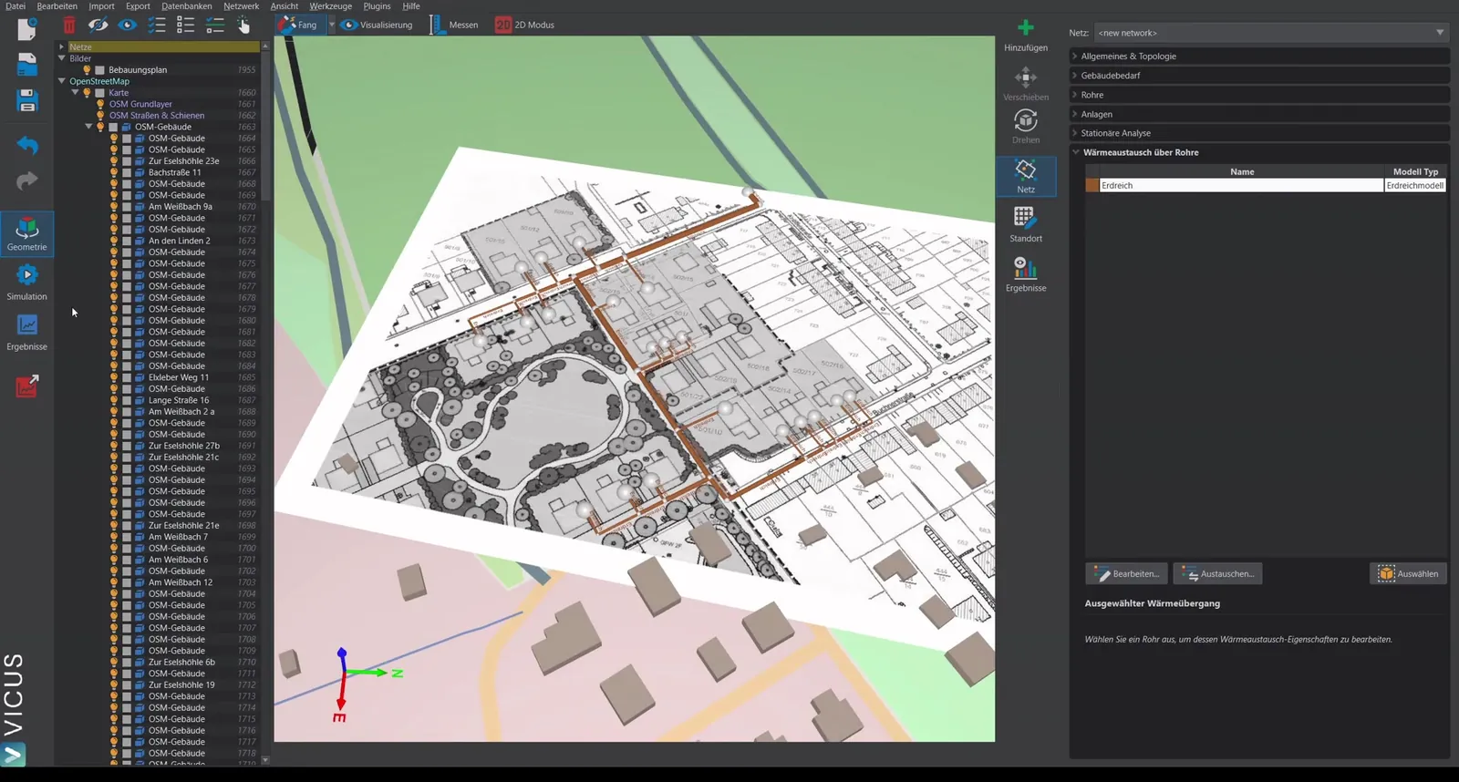
For the annual simulation, the following settings are recommended:
- Simulation duration: At least 2 years, so the ground can settle during the first year. The evaluation then refers to the second year (last 8760 hours).
- Disable fixed time step: With decentralized pumps, the option “Calculate the system only at fixed time steps” can be disabled. This often results in a faster and more stable simulation.
Important in practice
The ground has an enormous thermal inertia – a single simulation year still starts from unrealistic initial conditions and therefore yields source temperatures that are too optimistic. For this reason, always evaluate the second year (or, in the case of high extraction, a later one). For the final design, the long-term trend is also decisive: if the ground temperature drops year after year, the source is permanently overloaded.
Evaluating the results
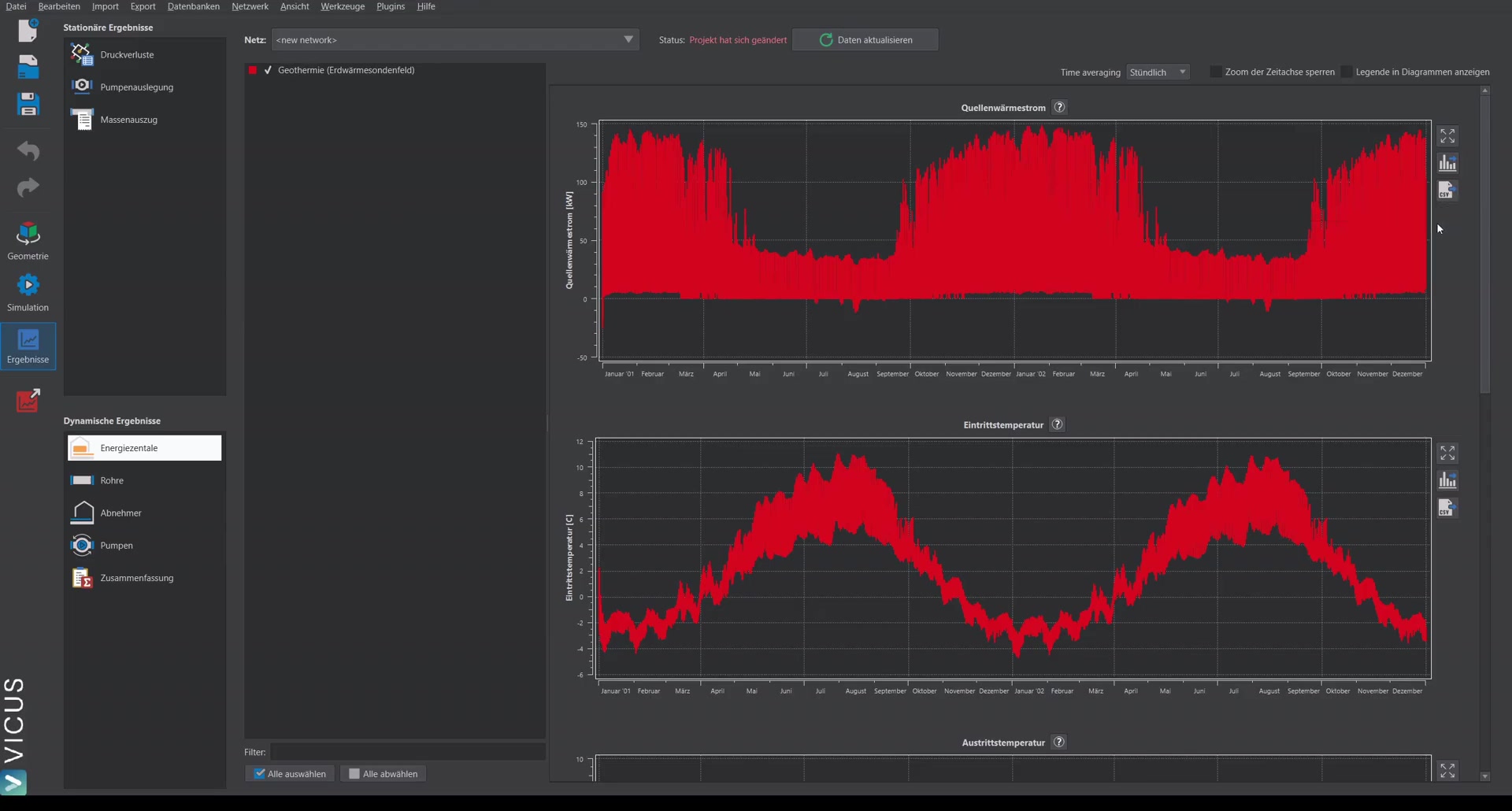
Energy plant (borehole field)
One important output is the source heat flux — the heat flux from the ground into the boreholes. It can be exported as a CSV file and used for a separate borehole simulation.
Iterative workflow
The recommended workflow for network simulation with a borehole field:
- Simulate the network with an assumed borehole temperature
- Export the source heat flux from VICUS Districts
- Apply the heat flux in the borehole simulation
- Import the resulting temperature back into VICUS Districts
- Iterate this procedure 2-3 times to obtain reliable values for the heat gains
Heat gains of the network
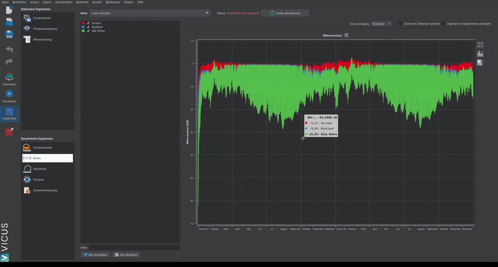
The heat gains of the network are displayed as “heat loss”. Negative values represent heat gains (heat flows from the ground into the network).
Additional results
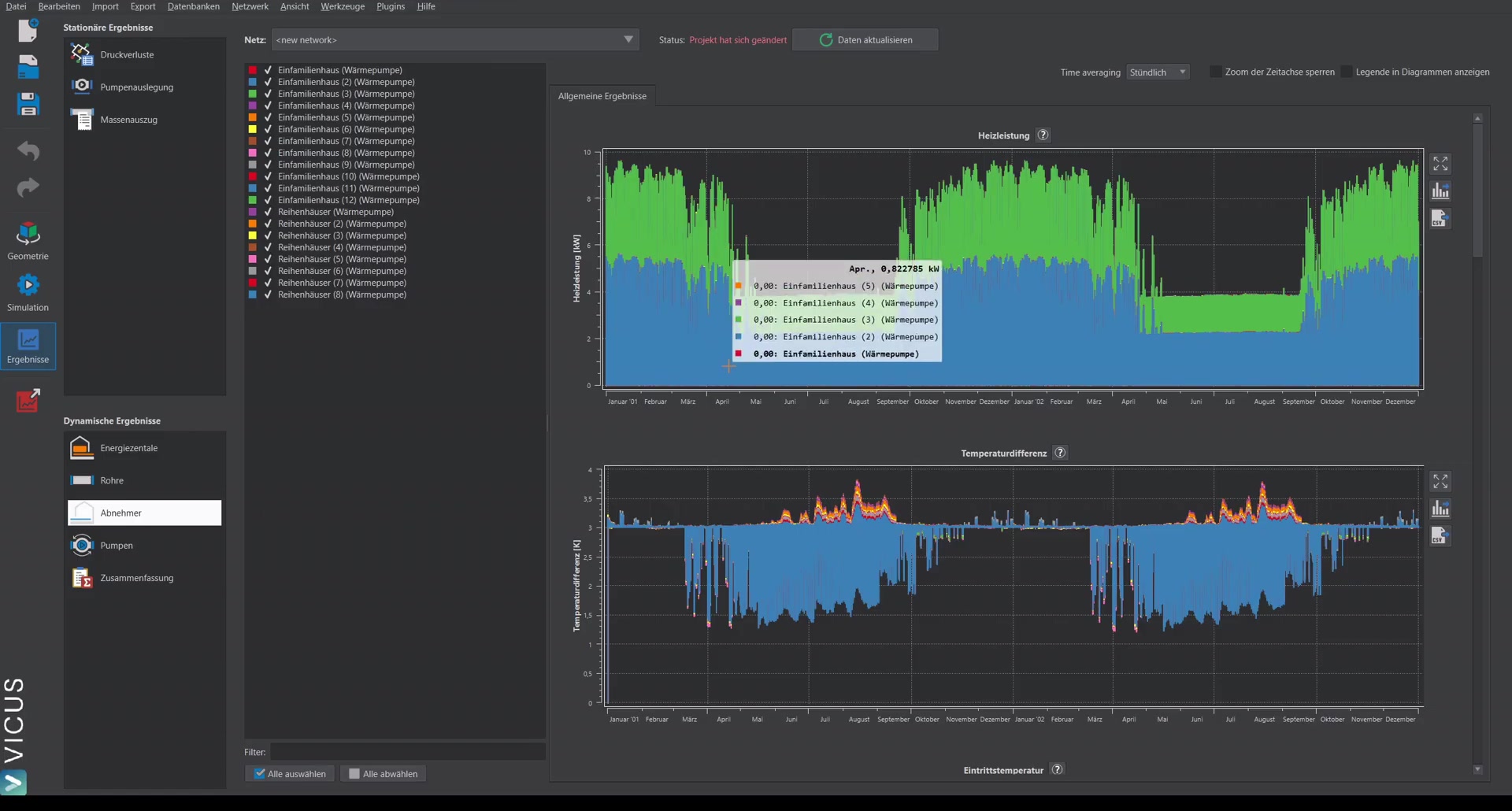
- Heating power of the heat pumps and temperature difference
- COP of the heat pumps: Often higher in winter (heating operation) and lower in summer (domestic hot-water operation only)
- Operating points of the pumps
Summary

The summary shows at a glance:
- Total supplied heat
- Heat extracted by the heat pumps
- Electrical energy demand of the heat pumps and circulation pumps
- Seasonal performance factor (e.g. approx. 4.2)
- Heat gains in absolute terms (MWh) and relative terms (percent)
The evaluation always refers to the last 8760 hours (one year).
External Post Processing
For more in-depth analyses, External Post Processing is available (it must be installed together with VICUS Districts). With it you can:
- Evaluate all simulation quantities individually
- Generate diagrams
- Visualize the temperature field in the ground around the pipes