Network settings and fluid
Define the network type and default templates for plants, heating curve and pipe heat exchange, and choose the fluid and display colors
Overview
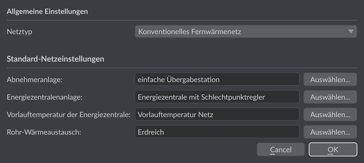
Every network has default settings that are used automatically in subsequent work steps: the network type as a preset package, as well as default templates for consumer and generator plants, heating curve and pipe heat exchange. In addition, the heat transfer fluid and the display colors of the network objects are defined on the Network tab.
How to open
- Menu Network > General settings …
- alternatively the Edit … button at General settings: on the
 Network tab, General & topology page
Both paths open the General settings dialog for the active network.
General settings dialog
General settings
| Field | Options | Meaning |
|---|---|---|
| Network type | Cold district heating network, LowEx heat network, Conventional district heating network | Preset package: the selection pre-populates the default network settings below with matching templates from the bundled database. All preset values can then be changed individually. |
| Minimum pressure margin | 0 to 100 bar, default 1.5 bar | Margin added to the vapour pressure at the hottest point of a pressure profile. Vapour pressure and margin together form the min. operating pressure the profile is checked against - in the status line of the path profile and in the network report. The value applies to the entire network. |
| Ambient pressure | read-only | Air pressure at the altitude of the project, computed from the z coordinate of the coordinate origin according to the standard atmosphere — not an input field. It is subtracted from the vapour pressure when the min. operating pressure is formed, because that one is an absolute pressure while the checked profile is a gauge pressure. 1.013 bar at sea level, 0.899 bar at 1000 m. |
The default of 1.5 bar for the minimum pressure margin is made up of 0.5 bar protection against evaporation and cavitation - on which there is broad professional consensus - and around 1.0 bar for the control tolerance of the pressure maintenance and for transients that a steady-state calculation does not resolve; this second component is a planning recommendation and not a standard. Binding are the technical connection requirements of the network operator, see Meeting operating pressure limits in heat networks.
Which quantity is checked, and with which further parameters, is described by Pressure Calculation in the Network.
Default network settings
All four fields are initially set to <not yet defined>, unless the network type has set a template, and are each selected from the database via Select…:
| Field | Meaning |
|---|---|
| Consumer plant: | Plant template (sub-network) that is assigned to automatically connected consumers, see Plant concept |
| Energy plant system: | Plant template for energy plants |
| Supply temperature of the energy plant: | Heating curve that specifies the supply temperature of the energy plant as a function of the outdoor temperature |
| Pipe heat exchange: | Default heat exchange model for all pipes of the network, see Heat exchange types |
The changes are applied with OK; the step can be undone as an undo action (Modified default network settings).
Choosing a fluid
The heat transfer fluid is defined on the Network tab, General & topology page, in the Fluid section. The display field shows the currently assigned fluid; without an assignment, the red note No fluid selected appears. The Choose fluid… button opens the database dialog in which a fluid is selected or newly created - see Fluids and other databases. The assignment applies to the entire network and is a prerequisite for pipe sizing and calculation.
Important in practice
Assign the fluid early - without an assignment the field reports No fluid selected, and neither pipe sizing nor steady-state calculation can be started. The fluid choice is also physically relevant: density, heat capacity and viscosity feed directly into mass flux and pressure loss. For cold networks with antifreeze, a glycol mixture gives noticeably different pump pressures than pure water.
Colors of the network objects
In the Legend section of the same page, four color buttons define the display colors of the node types and pipes:
| Entry | Object |
|---|---|
| Energy plant | Source node |
| Mixer | Branch node (created automatically during topology editing) |
| Consumer | Transfer stations |
| Pipes | Pipe routes |
Clicking a color button opens the color picker; the new color is applied immediately in the scene. The colors are display settings of the program (stored separately per display theme), do not belong to the project data, and are therefore not subject to undo.