Controller
Controlled quantities, P and PI controller types with parameters, constant and schedule-based setpoints, and index-point control in the heat network
Overview
In the simulation, controllers continuously adjust the manipulated variable of a component in order to keep a controlled quantity at its setpoint – for example the head of the controlled pump or the opening degree of the controlled valve. A controller is part of the component in the plant; the pump with controlled head and the controlled valve mandatorily require a controller.
Access
In the graphical plant editor, select a controlled pump or a controlled valve; in the component’s properties area you will find the Controller section. From there, the Edit controller dialog opens with the areas Controlled property and Control type.
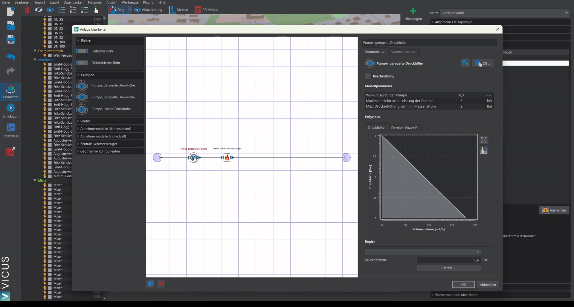
Controlled quantities
| Controlled quantity | Setpoint | Use case |
|---|---|---|
| Temperature difference of the following element | Temperature difference in K | Control the temperature spread across the following element (heat exchanger or heat pump), e.g. constant return temperature at consumers |
| Mass flux | Mass flux in kg/s | Hold a target mass flux in the element |
| Pressure difference at the index point | Pressure difference in bar | Pump control on the least favorable consumer (see index-point control below) |
| Outlet temperature on the secondary side of the following transfer station | from heating curve | Secondary-side supply temperature of the transfer station; the setpoint comes from the heating curve defined in the building demand of the consumers |
| Heating-power demand of the following element | Power of the following element | The head is controlled such that the prescribed (signed) heating/cooling power of the following heat generator is covered |
Quantities referring to a “following element” require a matching component directly behind the controlled element: for the temperature difference of the following element a heat exchanger or a heat pump, for the secondary-side outlet temperature a transfer station, for the heating-power demand an ideal heat/cold generator.
Good to know
The controller always takes its controlled quantity from the immediately following element. Therefore pay attention to the order in the circuit: if the matching component is not placed behind the controlled pump, the desired controlled quantity cannot be evaluated meaningfully. Place the reference element directly behind the control device.
Availability per component:
| Component | Selectable controlled quantities |
|---|---|
| Pump, controlled head | Mass flux, temperature difference of the following element, pressure difference at the index point, secondary-side outlet temperature, heating-power demand of the following element |
| Controlled valve | Mass flux, temperature difference of the following element, secondary-side outlet temperature |
Controller types and parameters
As control type, P and PI controllers are available. For the controlled quantities pressure difference at the index point and heating-power demand of the following element, the selection of the control type is omitted – here the manipulated variable is determined directly.
| Parameter | Unit | Meaning |
|---|---|---|
| Kp | – | Proportional coefficient |
| Ki | – | Integral coefficient (PI controller only) |
| Maximum controller output (Y-Max) | – | Limitation of the manipulated variable for temperature-difference and mass-flux control; for valves and heat exchangers the maximum zeta value. A value of 0 disables the limitation. |
| Min. temperature difference | K | Minimum temperature difference; only for the controlled quantity heating-power demand of the following element |
Setpoint: constant or schedule
- Fixed setpoint – the setpoint is entered directly in the dialog as a constant numeric value (temperature difference in K, mass flux in kg/s, pressure difference in bar).
- Schedule – the setpoint follows a schedule from the schedule database; depending on the controlled quantity, as a temperature-difference or mass-flux schedule. The schedule option is only available for temperature-difference and mass-flux control.
Two controlled quantities do not take their setpoint from a numeric value: for the secondary-side outlet temperature it comes from the consumers’ heating curve, for the heating-power demand of the following element from the prescribed power of the following element.
Index-point control
With index-point control, the controlled pump keeps the pressure difference at the least favorable point of the network at the setpoint: among the observed critical nodes, the one with the lowest pressure difference is controlled. If the pressure difference drops there, the pump increases its head – this way the network is operated only with as much pressure as the most distant consumer actually requires.
The critical nodes to be observed are defined in the component editor under Index point: via the Selection … button. The setpoint is the pressure difference in bar.
Alternatively, index-point control is also available without a detailed plant: in the simplified energy plant as pump control mode Index-point controller with the parameter Differential pressure at the consumer (bar) – see plant concept.