Fittings (pipe fittings)
Automatic assignment of fittings at network nodes: bends, tees, parallel branches, reducers and pressure-loss coefficients
Overview
VICUS Districts automatically assigns fittings (pipe fittings) to the nodes of the heat network: bends at direction changes, tees or parallel branches at branchings, as well as reducers and expansions at diameter changes. The fittings enter the pressure-loss calculation with their pressure-loss coefficients (zeta values) and appear in the bill of materials. The assignment is performed automatically after every pipe sizing and can be triggered again manually.
Opening
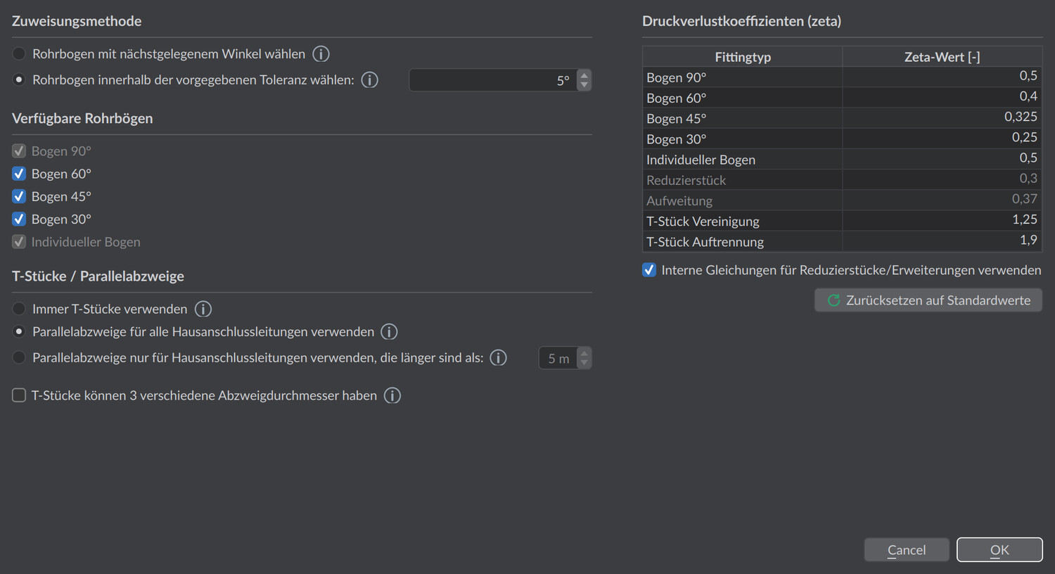
- Settings: Pipe fittings settings … button in the Network > Size pipes … dialog (Network properties section) - opens the Pipe fittings settings dialog
- Recalculation:
 Recalculate pipe fittings … button in the Pipes tab of the network properties window
Bends
In the Assignment method section it is defined how direction changes along a route are mapped to standard bends:
| Option | Default | Meaning |
|---|---|---|
| Choose pipe bend with nearest angle | selected | Each bend receives the available standard bend (90°, 60°, 45° or 30°) whose nominal angle is closest to the actual bend angle - regardless of the deviation. Individual bends are not created in this mode. |
| Choose pipe bend within the given tolerance: | Tolerance 5° | A standard bend is only used if the bend angle lies within the tolerance of an activated bend type; otherwise an individual bend with its own zeta value is assigned, which keeps the exact angle. |
In the Available pipe bends section, check boxes define which bend types the assignment may use: Bend 90° is always active and cannot be deselected; Bend 60°, Bend 45° and Bend 30° are optional. The Individual bend check box is controlled automatically by the assignment method: it is activated with the tolerance method and deactivated with the nearest-angle method.
Tees and parallel branches
In the Tees / parallel branches section it is determined how branchings - especially house connections - are modeled:
| Option | Meaning |
|---|---|
| Always use tees | Every branching, including house connections, is modeled as a right-angled tee – the simplest topology. |
| Use parallel branches for all house connection lines (default) | Every house connection is modeled as a parallel branch: the connection line first runs for a distance parallel to the main line before it bends off. This reproduces the construction form commonly used in practice for house connections of buried pre-insulated lines (cf. AGFW FW 401). |
| Use parallel branches only for house connection lines longer than: | Parallel branch only for connection lines above the threshold length (default: 5 m); shorter stubs receive a simple tee. |
The choice affects only the modeled branching topology and thus the fittings reported in the bill of materials and the associated pressure loss. VICUS Districts does not compute the mechanical thermal expansion of the lines themselves – it is, however, the decisive planning reason for the choice of construction form (see note below).
Additionally:
| Option | Default | Meaning |
|---|---|---|
| Tees can have 3 different branch diameters | disabled | Allows tees with three different diameters (main line inlet, main line outlet, branch). Such tees are manufacturer-specific; when disabled, the main line keeps one diameter and only the branch may differ. |
At diameter changes along a route, reducers (in the supply) or expansions (in the return) are inserted automatically.
Good to know
In the real construction, the parallel branch absorbs the axial thermal expansion of the main line before it reaches the weld seam of the branch as thrust; a rigid right-angled tee transfers this expansion directly into the seam. This is why the parallel branch is the standard solution for buried pre-insulated lines. VICUS Districts does not compute this thermal expansion or the resulting stresses – nevertheless you should keep the default so that your model (fittings, lengths, pressure loss) matches the later construction, unless your laying system explicitly calls for tees.
Pressure-loss coefficients (zeta values)
The Pressure-loss coefficients (zeta) table lists the zeta value [-] per fitting type; the values are editable. Default values:
| Fitting type | Zeta value [-] |
|---|---|
| Bend 90° | 0.5 |
| Bend 60° | 0.4 |
| Bend 45° | 0.325 |
| Bend 30° | 0.25 |
| Individual bend | 0.5 |
| Reducer | 0.3 |
| Expansion | 0.37 |
| Tee combining | 1.25 |
| Tee dividing | 1.9 |
Supply and return are treated separately: in the supply, tees act as dividing and diameter changes as reducers; in the return as combining or expansions.
If Use internal equations for reducers/expansions is activated (default), the zeta values of the reducer and expansion are not taken from the table but calculated from the diameter ratio (referred to the smaller inner diameter , larger diameter ):
The Reset to default values button restores all zeta values to the default values above.
Recalculation
The fittings are assigned automatically after every pipe sizing. After manual changes (e.g. swapping the pipe of individual routes), Recalculate pipe fittings … in the Pipes tab triggers the assignment again; the Pipe fittings settings dialog opens first, then the assignment is performed. Nodes locked for sizing are skipped in this; a message states the number of nodes left out.
Display in the model
In the Pipes tab the Pipe fitting properties display mode shows the fitting assignment color-coded in the model. The legend distinguishes the categories Valid (green), Invalid (red) and Not assigned (yellow); via the  Select button the nodes of the selected category can be selected in the scene. If invalid fittings are present, a notice banner with their number points this out. When a node is selected, a table shows the fittings assigned there with name and count.