Create and size the network
Cold district heating, part 1: create a cold district heating network in VICUS Districts and define the pipe dimensions
Overview
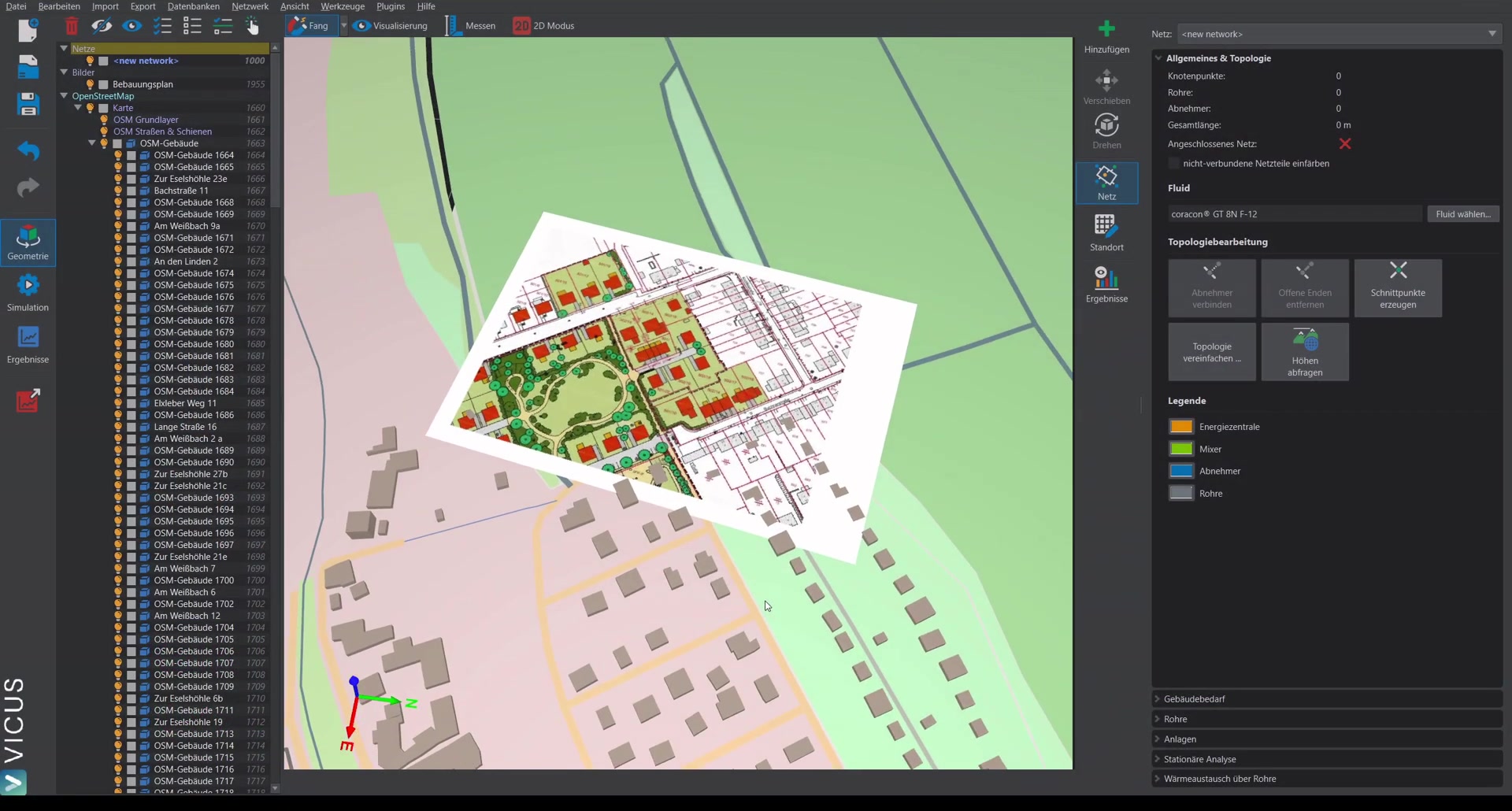
This part shows how a cold district heating network is created in VICUS Districts. In the first step, the consumers and the network are drawn, and then a pipe sizing is performed.
As a starting point, we use a project in which an OpenStreetMap section and a development plan for a new-build area have already been imported.
Preparing the development plan
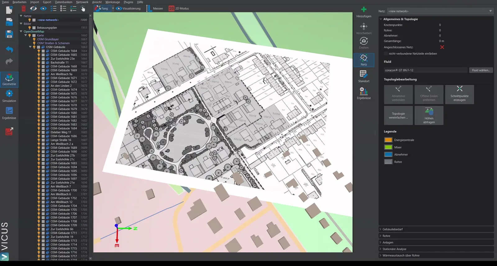
To improve clarity during planning, the imported development plan can be adjusted:
- Double-click the DXF drawing in the navigation tree.
- Turn the saturation all the way down for a better overview.
Drawing consumers
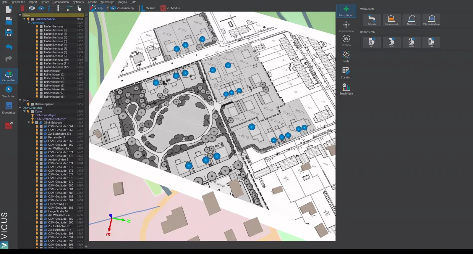
The consumers (buildings) are placed at the positions where the heat pumps are to be connected.
- Click on Consumer and set the building positions on the plan.
- Select an energy standard (e.g. GEG reference house).
- Assign the heating power (e.g. 12 kW for single-family houses).
- As a name, you can enter “Single-family house”, for example.
- The connected to a heat pump checkbox is already set, as is a COP at design conditions.
COP at design conditions
The COP is used only for the steady-state calculation, i.e. the pipe sizing. It serves to distinguish between the building’s heating power and the heat pump’s evaporator power on the cold side. The evaporator power is the decisive quantity for network sizing.
Adding further consumers
Additional consumers (e.g. row houses with 7 kW heating power) can be drawn in the same way. The remaining settings stay identical.
Drawing the network
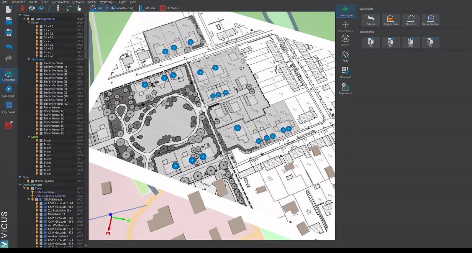
- Start at a suitable location and draw the network along the planned route.
- Confirm with Enter — once to close the polyline and again to create the network line.
- Draw additional lines. The software automatically snaps to existing edges.
- Overhanging lines can be trimmed afterwards.
Drawing the energy plant
- Position the energy plant at the desired location (e.g. for a borehole field).
- Assign a name (e.g. “Geothermal”).
- Click Create energy plant.
Connecting consumers and energy plant
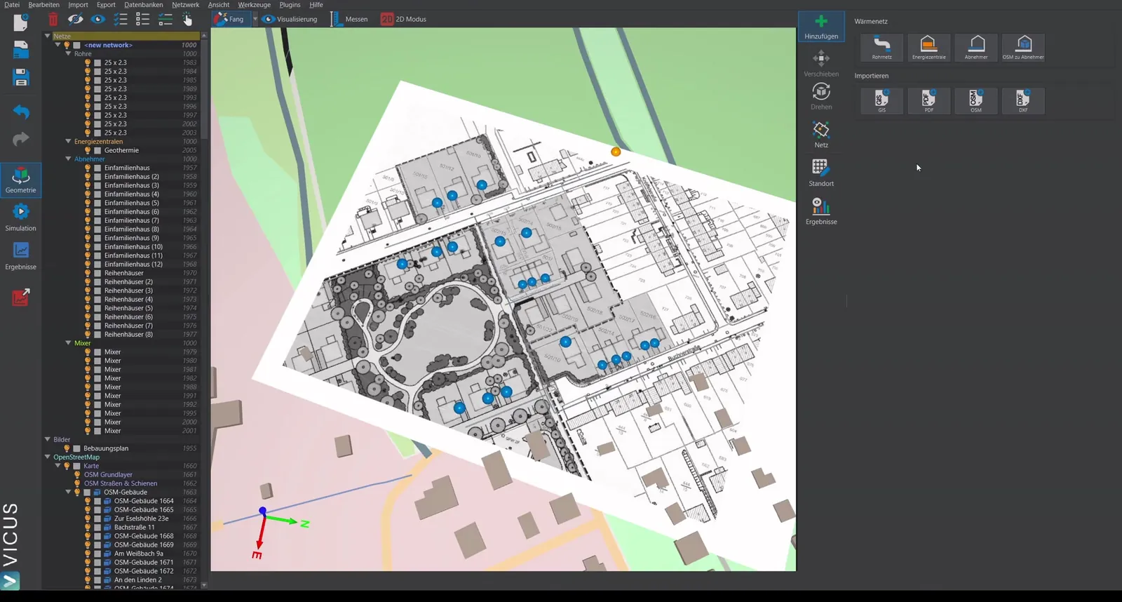
- Switch to network mode.
- Click Connect consumers — both the consumers and the energy plant are automatically connected to the network.
- Select Remove open ends to obtain a valid network topology.
Note on the fluid
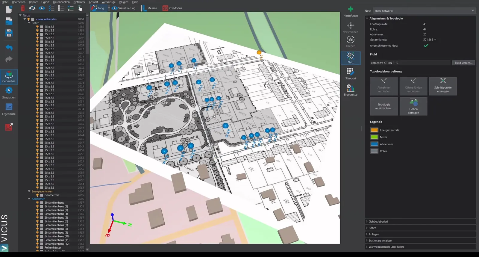
When the project is created as a cold district heating network, a glycol-based fluid is already preset. It provides frost protection and accounts for the higher viscosity at low temperatures, which is relevant for the pressure-loss calculation.
Checking the connection load
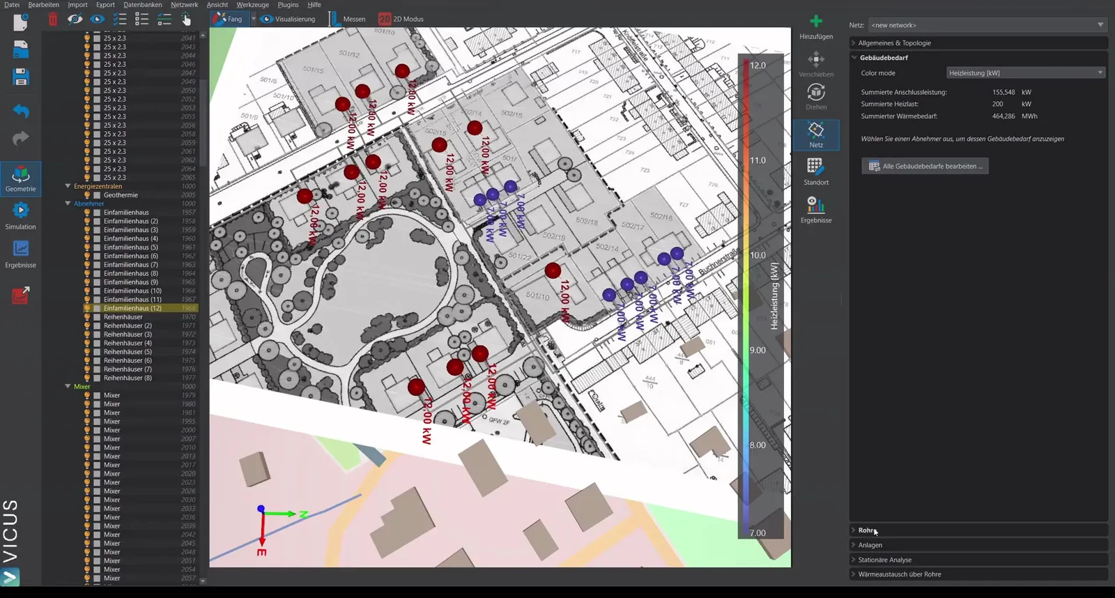
On the next tab, the connection load is displayed. This does not correspond to the building’s heating power but to the evaporator power on the cold side of the heat pump.
When clicking a consumer, a dynamic profile together with all values for heating power and heating energy demand are already stored. These can be changed flexibly at any time.
Performing the pipe sizing
- Switch to the Pipes tab.
- Click Size pipes.
- Set the supply temperature (e.g. 0 °C — a rather safe value, since the fluid becomes more viscous at lower temperatures).
- Set the temperature spread to 3 Kelvin.
- Select the available pipes. For a cold district heating network, uninsulated pipes are used in order to take advantage of the heat gains from the ground. Holding the Shift key lets you select several entries at once.
- Enable the simultaneity factor for the sizing.
- Perform the sizing (e.g. at 100 Pa/m pressure loss).
Good to know
What is a loss in a warm network is desirable in a cold one: the uninsulated pipes act as a distributed ground heat source in their own right. Over the large pipe surface, the cold fluid picks up additional heat from the ground on its way and thereby relieves the actual source. This is why a cold network is deliberately planned without insulation – and the network length becomes a usable heat gain.
Displaying results
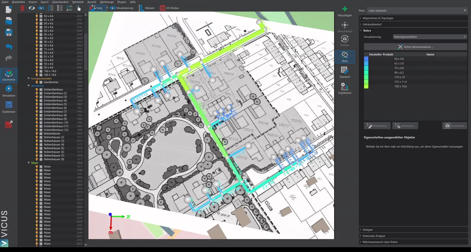
Once the sizing is complete, the results can be visualized:
- The pipe dimensions are shown in the network plan.
- Via Results > Bill of materials, you obtain a listing of all pipes and pipe fittings.