Running pipe sizing
The Size pipes dialog: all options, the calculation workflow and manual rework of individual routes
Overview
The Size pipes dialog runs the automatic pipe sizing for the active network: it defines the fluid temperature, temperature difference, pipe selection and sizing criterion, and then assigns a pipe type to each route. After sizing, the fittings at the nodes are assigned automatically. The underlying calculation model is described in Calculation method.
Opening
- Menu Network > Size pipes …
- alternatively the
 Size pipes … button in the Pipes tab of the network properties window
Prerequisite: the network must be fully connected, otherwise an error message appears and the dialog does not open.
General tab
Network properties
| Option | Default | Unit | Meaning |
|---|---|---|---|
| Fluid temperature: | auto (empty) | °C | Nominal supply temperature to determine the temperature-dependent fluid viscosity. The field may be left empty (auto); the supply temperature is then determined from the plants or the heating curve of the network. |
| Temperature difference: | 4 | K | Nominal temperature difference between supply and return at the transfer stations; converts the consumer load into a mass flux. |
| Available pipes: | - | - | Number of the selected pipe types. The Select pipes … button opens a database dialog with a selection column: via the check boxes or the buttons to select and deselect you define which pipe types the algorithm may use. |
| Pipe fittings: | - | - | The Pipe fittings settings … button opens the settings dialog for the automatic fitting assignment, see Fittings. |
Sizing criteria
| Option | Default | Meaning |
|---|---|---|
| Sizing load: | Connection load | Connection load uses the installed connection load of each transfer station; part-load fractions are not taken into account. Actual maximum power uses the maximum of the actual consumer demand from the assigned demand profile. Heating and cooling are both considered; whichever imposes the larger load on the network is decisive. With a configured heat pump only the source-side share of the heating power loads the network (), while a cooling load is rejected into the network unchanged. The part-load fraction entered for each consumer applies in addition. In both cases the simultaneity factor is applied when simultaneity is activated. |
| Sizing method: | Maximum allowed pressure loss per pipe length | Criterion for the pipe selection per route: Maximum allowed pressure loss per pipe length or Maximum pump head (switches the input fields below). |
Method: Maximum allowed pressure loss per pipe length
| Option | Default | Unit | Meaning |
|---|---|---|---|
| Maximum pressure loss per pipe length: | 150 | Pa/m | Maximum allowed pressure loss per pipe meter. For each route the smallest available pipe is chosen that stays below it. |
| Maximum velocity by DN: | disabled | - | Activates an additional velocity limit per nominal diameter. |
With the velocity limit activated, a table with the columns DN [mm] and Max. velocity [m/s] appears; the velocity values are editable (multiple selection possible). A chart shows the table values as a solid curve (v_max) and the velocities calculated from the pressure-loss limit as a dashed reference curve (v(dp_max)).
 Update velocities recalculates the velocity limits from the currently set pressure-loss limit (iterative calculation with Colebrook friction coefficient and a roughness of 0.01 mm, see Calculation method). A query confirms overwriting the table.
 Copy copies the table to the clipboard.
Method: Maximum pump head
| Option | Default | Meaning |
|---|---|---|
| Type of supply: | Central circulation pump | Central circulation pump: the table lists the energy plants (source nodes). Decentralized circulation pumps: the table lists the transfer stations of the consumers. |
| Table Node name / Pump head [bar] | - | Available head per pump in [bar], editable; with a multiple selection the entered value is applied to all selected rows. |
With this method the pipes are first pre-assigned according to the maximum pressure loss per pipe length and then corrected so that the total pressure loss along each supply path stays within the available pump head.
Energy plant distribution assumptions tab
This tab is only active if the network contains at least one energy plant, and corresponds to the dialog under Network > Energy plant distribution assumptions …, see Multiple energy plants.
Workflow and result
The Run pipe sizing button starts the calculation; the progress is shown in a progress bar and can be canceled. If simultaneity is activated and no up-to-date results exist, the simultaneity optimization is run first. After completion:
- Each non-locked route has a pipe type assigned; afterwards the fittings at the nodes are reassigned automatically.
- Routes for which no pipe satisfies the criterion receive the largest available pipe and are listed in a warning message.
- With the maximum pump head method a warning appears if the specified head is not sufficient.
- Locked pipes and nodes are skipped and listed in a notice message after a successful sizing.
The change is transferred into the project as an undo step. If Close dialog after completion is activated (default), the dialog closes automatically after a successful completion.
Manual rework
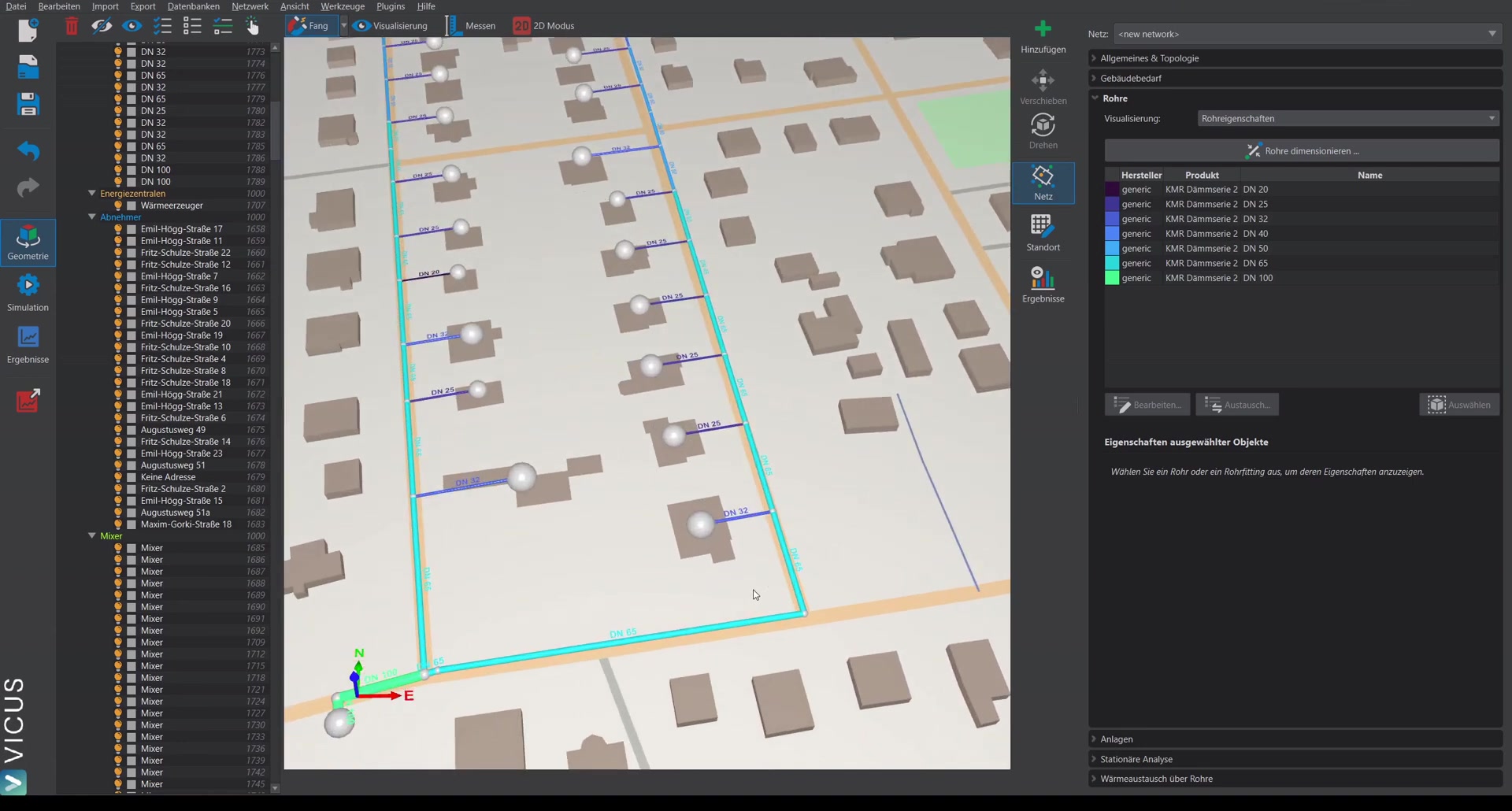
Individual routes can be reworked in the Pipes tab of the network properties window:
- The table in the Pipe properties display mode lists all pipe types used in the network with color, manufacturer, product and name.
 Edit… opens the selected pipe type in the pipe database.
 Exchange… replaces the selected pipe type throughout the network with another one.
 Select selects all routes with this pipe type in the 3D scene.
For individual routes selected in the scene, Assign from DB… and Assign from table directly assign a different pipe type. When editing locked routes a safety query is issued.
By the way
After a manual pipe swap it is worth recalculating the fittings - a different pipe type changes the diameters at the nodes and thus the reducers and tees. With Exchange… you replace a pipe type network-wide in a single step, which saves a lot of manual work when product ranges are swapped afterwards.