Network Model and Terminology
Data model of a heat network in VICUS Districts: node types, routes, supply/return logic and the property tabs of the network panel
Overview
A heat network is modeled in VICUS Districts as a graph of nodes and routes (edges). Nodes are consumers, pipe fittings or energy plants; routes connect the nodes and carry the pipe assignment. All further tools work on this model: pipe sizing, steady-state calculation and dynamic simulation.
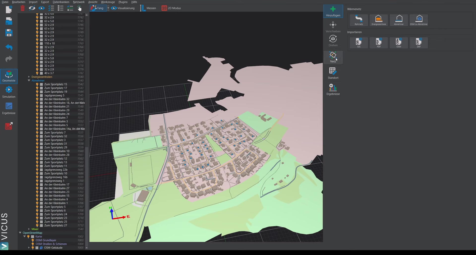
Node types
Each network node has exactly one of the three types:
| Type | English keyword | Meaning |
|---|---|---|
| Transfer station | SubStation | Connection node of a building or consumer. Carries the heat demand (connection load) that is used for pipe sizing and simulation. |
| Mixer | Mixer | Branch or intermediate node along the route (pipe fitting), e.g. at branches and changes of direction. Carries no heat demand. |
| Source | Source | Energy plant or feed-in node. Here the heat is generated or fed in; plant components such as pumps and heat generators can be assigned to a source. |
Color legend
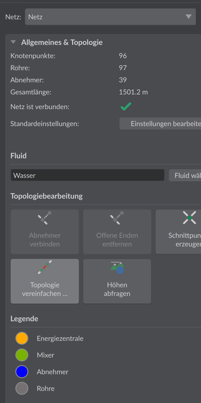
In the General & topology tab of the network panel, the Legend group shows the display colors and allows them to be adjusted:
| Legend entry | Object |
|---|---|
| Pipes | Routes (edges) |
| Consumers | Consumer nodes of the network |
| Energy plant | Nodes of type source |
| Mixer | Nodes of type mixer |
Routes and pipe assignment
A route (edge) connects two nodes and references a pipe from the pipe database. The route length results from the geometry. Pipes can be assigned manually or sized automatically.
Supply/return logic: Each route is drawn only once in the scene but represents the pipe pair of supply and return. When exporting to the simulation model, supply and return lines are automatically generated from it. In addition, each route has the attribute Allow automatically generated connections: only at such routes may consumers be connected by the automatic connection function – this makes it possible to distinguish house connection lines from distribution lines.
Network statistics
The General & topology tab shows key figures of the active network:
| Display | Meaning |
|---|---|
| Nodes: | Number of all nodes |
| Pipes: | Number of routes |
| Consumers: | Number of consumer nodes |
| Total length: | Sum of all route lengths in m |
| Network is connected: | Check mark if all nodes and routes form a single connected graph. Otherwise the option Show network parts (colors each connected subgraph differently) and the button Find network parts appear. |
A network that is not connected cannot be calculated meaningfully – check this display before sizing and simulation.
Important in practice
Make the Network is connected: display your fixed control step before you size or simulate. If the check mark is missing, there is almost always a route that is not quite closed or a node that was not snapped. With Show network parts you color each connected subgraph and quickly find the break point – often it is enough to reconnect two nodes with object snapping active.
Property tabs of the network panel
The network panel on the right is divided into six tabs:
| Tab | Content |
|---|---|
| General & topology | Network statistics, default settings, fluid, topology tools (connect consumers, remove open ends, create intersections, simplify topology, query elevation data) and legend. See Topology tools and Network settings. |
| Building demand | Properties of the transfer stations: connection load or demand time series of the buildings. See Building demands. |
| Simultaneity and part load | Simultaneity factor of the network and part-load assumptions for sizing. See Simultaneity. |
| Pipes | Pipe assignment of the selected routes, pipe properties, pipe fittings and access to sizing. See Performing pipe sizing. |
| Plants | Plant configuration at source and consumer nodes (pumps, heat generators, transfer stations). See Plants concept. |
| Heat exchange via pipes | Heat exchange of the pipes with the surroundings, e.g. ground model for buried lines. See Heat exchange types. |
Above the tabs, the Network: combo box selects the active network – relevant as soon as the project contains multiple networks.