User Interface and Navigation
Layout of the user interface, switching between the building and network workspaces, camera navigation, object snapping, selection and visualization options
Overview
VICUS Districts is the heat-network workspace of the VICUS environment: the navigation tree, 3D scene and property panel are geared towards planning heat and cooling networks. This page describes how to switch workspaces, the layout of the interface, camera navigation in 2D and 3D, object snapping and the selection of network objects.
Switching the workspace
- The menu View > VICUS Workspaces > Heat Network activates the network workspace, View > VICUS Workspaces > Building the building workspace.
- Both menu entries can be enabled and disabled independently: at least one workspace is always active, and both can be active at the same time.
The active workspaces determine which tools are shown in the interface. When the network workspace is active, the button  Network in the toolbar to the left of the 3D scene opens the network property panel.
Layout of the interface
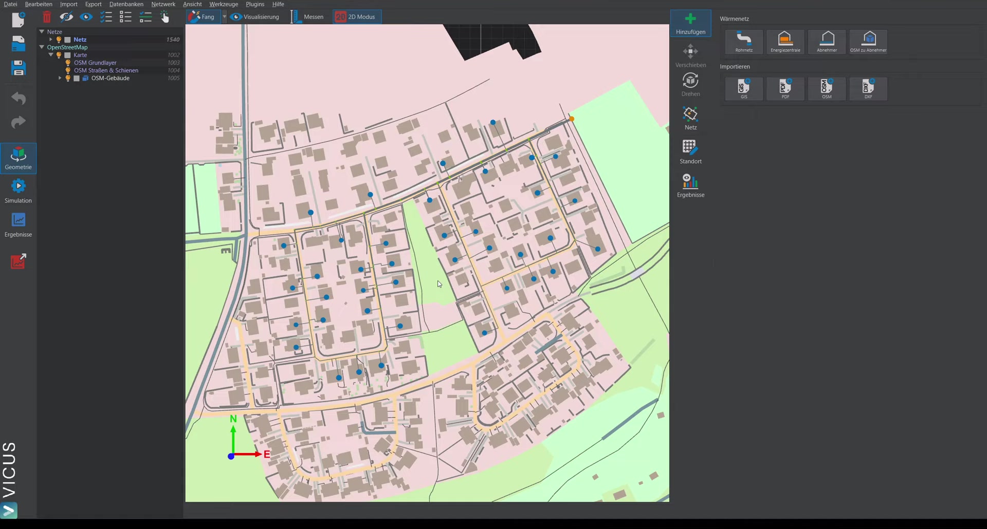
| Area | Function |
|---|---|
| Navigation tree (left) | Lists all networks with their nodes and routes. In front of each entry, the light-bulb icon toggles visibility and a selection icon selects or deselects the object; a double-click on the name renames the object (with undo). The active network is shown in bold. For details see Object Tree. |
| 3D scene (centre) | Interactive representation of the network. A toolbar above the scene provides Snap, Visualization, Measure and 2D mode. |
| Property panel (right) | Shows the properties of the active network and of the selected objects, organized into tabs (see Network model and terminology). |
The toolbar of the navigation tree offers the following actions:
| Action | Shortcut |
|---|---|
| Remove | Del |
| Show selected objects | F7 |
| Hide selected objects | F6 |
| Select all | Ctrl+A |
| Deselect all | Esc |
| Smart selection (select by properties) | Ctrl+F |
| Invert selection | Ctrl+I |
2D and 3D view
By default the scene is rendered in perspective (3D). For to-scale top-down views – the usual case in network planning – there are two toggles:
- The menu View > Parallel projection (2D) – switches between perspective and parallel projection.
- The button
 2D mode in the toolbar above the scene – orthographic top-down view.
Fixed camera viewpoints are available via the View menu or directly by shortcut:
| View | Shortcut |
|---|---|
| View from above | Ctrl+5 |
| View from north / south | Ctrl+2 / Ctrl+8 |
| View from east / west | Ctrl+4 / Ctrl+6 |
| Bird’s-eye view from north-east / north-west | Ctrl+9 / Ctrl+7 |
| Bird’s-eye view from south-east / south-west | Ctrl+3 / Ctrl+1 |
Camera navigation
| Input | Effect |
|---|---|
| Drag with left mouse button | Rotate the camera around the clicked point (orbit) |
| Drag with middle mouse button | Pan the view |
| Drag with right mouse button | Free camera rotation (first-person) |
| Mouse wheel | Zoom towards the mouse pointer |
| W / A / S / D | Move camera forward / left / back / right |
| R / F | Raise / lower the camera |
| Q / E | Rotate the camera about the vertical axis |
| Spacebar (hold down) | Movement 10× faster |
| Shift (hold down) | Slowed movement (fine adjustment) |
A complete reference of all key and mouse assignments can be found under Keyboard and mouse.
Selection in the scene
- Clicking a node or route selects the object and replaces any existing selection. Ctrl+click adds objects to the selection or deselects them individually.
- Ctrl + drag with the left mouse button opens a selection window: dragging from left to right selects all touched objects, dragging from right to left only fully enclosed objects. Dragging upwards deselects objects instead of selecting them.
- Esc clears the entire selection.
Object snapping
The button  Snap in the toolbar above the scene, or the F3 key, toggles object snapping on and off. With snapping active, the local coordinate system snaps – while drawing and editing – onto the nearest snap target within an adjustable search radius, for example onto existing network nodes and pipe routes, onto the grid, or onto points and lines of imported drawings and OSM buildings. This produces exact connections to the existing network or a site plan, without having to align points by hand.
With snapping active, an additional button opens the Snap options dialog, in which the individual snap targets can be enabled in groups and the snap distances can be set. The complete reference of all snap targets can be found under Drawing the network.
Visualization options
The button  Visualization in the toolbar above the scene reveals the settings for the network visualization:
| Option | Meaning |
|---|---|
| Scale consumers | Display size of the consumer nodes (slider) |
| Scale pipes | Display diameter of the pipes in the scene (slider) |
| Text | Show/hide labels on nodes and pipes |
| Scale text | Font size of the labels (slider) |
| Uniform text color | Color all labels in a single selectable color rather than per object |
Scaling affects only the display, not the underlying pipe diameters or connection loads.
In practice
With large networks, the displayed Text labels can noticeably slow down the rendering. Hide them for smooth navigation and turn them back on only selectively when needed. With Scale consumers and Scale pipes you additionally enlarge small elements purely visually – without changing the actual pipe diameters.
Measure (distance measurement)
The Measure button in the toolbar above the 3D scene activates the distance measurement mode. The start and end points are set by clicking in the scene; a small window displays the measured values:
| Field | Meaning |
|---|---|
| Distance: | Direct distance between start and end point [m] |
| Start point: / End point: | Coordinates of the two points (x, y, z) [m] |
| Offset: | Difference Δx, Δy, Δz between the points [m] |
The color button lets you change the color of the measurement line (default: red). The Copy information button places all values, tab-separated, on the clipboard. Clicking Measure again leaves the measurement mode.
Location: grid and world-coordinate origin
The Location editing mode (toolbar to the left of the scene) combines the grid settings and the georeferenced origin.
Grid settings – display of the ground grid (main grid at z=0):
| Field | Meaning | Default |
|---|---|---|
| Extent: | Overall size of the ground grid [m] | 500 |
| Spacing of the main grid lines: | Spacing of the main lines [m] | 10 |
| View depth: | Camera view range (far plane) [m] | 10000 |
World-coordinate origin – shows the georeferenced origin of the project: the coordinates X:, Y:, Z: [m] and the UTM zone:. These values are set during import or georeferencing and are only displayed here. For heat networks the Z origin is particularly relevant, because the network nodes are positioned relative to it.
The ground grid set here (main grid at z=0) must not be confused with the snap grid of the Snap tool – the latter only controls the raster snapping while drawing.
Display options in the “View” menu
Further toggles are available in the View menu:
| Menu entry | Effect |
|---|---|
| Show IDs in the navigation tree | Shows the numeric IDs of the objects in the navigation tree – helpful for matching against result quantities, exports and messages |
| Show main grid at z=0 | Shows/hides the line grid of the ground plane (see Location) |
| Show ground plane | Shows/hides the filled ground plane (only visible when the Building workspace is active) |
| Reset view | Resets the camera: view from the north onto the centre of the terrain |
| Find selected geometry (Ctrl+G) | Positions the camera near the currently selected objects |
Network examples on the start page
The start page of VICUS Districts contains, next to Recently used projects, the Network examples tab with ready-made example projects for heat networks. A click opens the respective project – a good way to get to know the interface and the workflows.