Geothermal energy & heat sources
Geothermal components and heat sources: borehole field, horizontal geothermal collector with coupled ground model, source heat exchanger with UA value
Overview
These components integrate heat sources into the network – typically in the plant of the energy plant or as the source of a cold district heating network. Borehole heat exchangers and collectors are hydraulically flowed-through components with a ground boundary condition; the source heat exchanger couples any external source to the network via a UA value.
Borehole field
A field of vertical borehole heat exchangers. The model computes the pressure loss from the borehole geometry and the heat exchange against the borehole temperature (temperature of the grout), which is prescribed as a time series – usually from an external borehole-field simulation (e.g. EED) or from measurement data.
| Parameter | Unit | Default | Meaning |
|---|---|---|---|
| Borehole depth | m | 100 | Depth of each borehole |
| Number of boreholes | – | 10 | Number of boreholes in the field |
| Borehole type | – | Two parallel pipes | Two parallel pipes (double-U) or Simple single pipe |
| Pipe | – | from pipe database | Borehole pipe (diameter, roughness) |
The temporal development of the ground temperature over the operating years is not simulated internally – it is contained in the prescribed borehole temperature time series. For long-term considerations (regeneration, cooling-down) this time series must be generated accordingly.
Important in practice
Be aware of the model boundary: for statements on regeneration or cooling-down of the borehole field over the operating years, you must first generate the borehole temperature time series with a suitable borehole-field tool (e.g. EED) and pass it in here. The horizontal collector with a coupled ground model, by contrast, computes the ground temperature itself – including the feedback of the heat extraction.
Geothermal collector
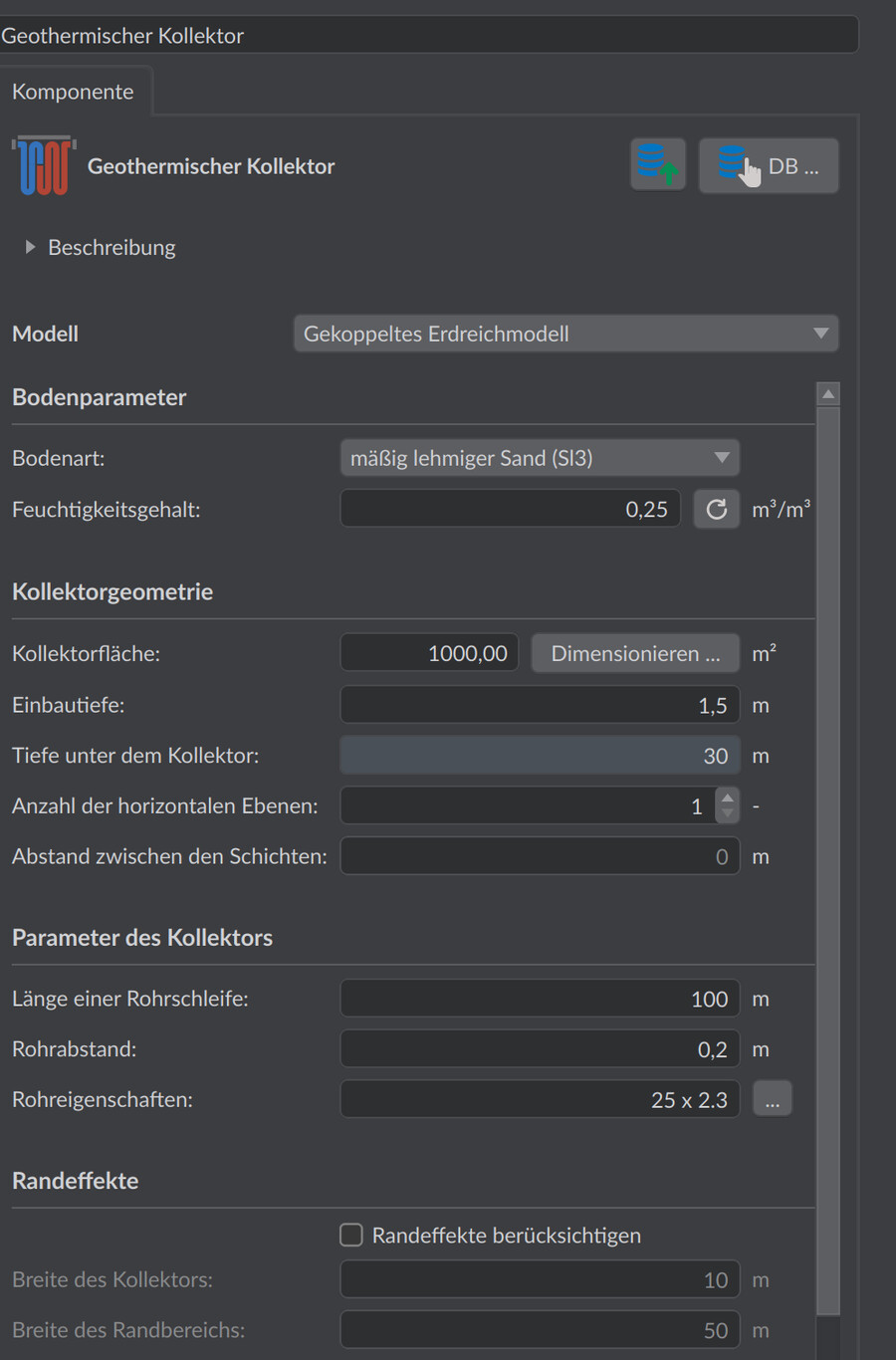
A horizontal ground heat collector with one or two pipe layers. Two operating modes:
- Coupled ground model: a finite-volume model of the ground is generated and coupled with the network simulation. The model takes into account the climate boundary condition at the ground surface, heat conduction in the soil as well as ice formation; the soil moisture is assumed to be uniformly distributed. Optionally, edge effects are taken into account – the model then becomes two-dimensional and considerably more computationally intensive. For large collectors or first estimates, the one-dimensional model without edge effects is sufficient.
- Fixed temperature: the ground temperature is prescribed as a constant value or time series (fast, but without feedback of the heat extraction).
| Parameter | Unit | Default | Meaning |
|---|---|---|---|
| Collector area | m² | 1000 | Occupied ground area |
| Length of one pipe loop | m | 100 | Length of one pipe circuit; the number of parallel circuits follows from area and pipe spacing |
| Collector width | m | 50 | Width of the field (for the edge-effect calculation) |
| Laying depth | m | 1.5 | Depth of the (upper) pipe layer |
| Pipe spacing | m | 0.2 | Spacing of parallel pipes within a layer |
| Number of horizontal layers | – | 1 | 1 or 2 pipe layers |
| Layer spacing | m | 1.0 | Vertical spacing with two layers |
| Soil type | – | moderately loamy sand | Soil type according to DIN 4022; determines the thermal material properties |
| Soil moisture | m³/m³ | 0.246 | Volumetric water content; influences thermal conductivity and ice formation |
| Edge width | m | 10 | Width of the co-modeled edge strip (only with edge effects) |
The coupled ground model uses the same soil physics as the ground model of the routes.
Source heat exchanger
The source heat exchanger couples an external heat source to the network via a fixed UA value – suitable for waste heat, surface water or a lump-sum represented source:
The source temperature is prescribed via the Heat exchange tab as a constant value or time series (required). If it lies above the fluid temperature, the network is heated; if it lies below, it is cooled – the component is thus also suitable for representing re-cooling.
| Parameter | Unit | Default | Meaning |
|---|---|---|---|
| UA value | W/K | 1000 | Heat transfer capacity |
| Nominal volume flow | m³/h | 2 | Reference volume flow for the pressure loss |
| Nominal pressure loss | bar | 0.5 | Pressure loss at the nominal volume flow (quadratic scaling) |
| Fluid volume | L | 3 | Fluid volume |
Notes
- The collector with a coupled ground model and edge effects is the most computationally intensive component – plan for longer simulation times or, for variant studies, do without the edge effects at first.
- The ground boundary conditions of the routes (pipe heat losses to the ground) are treated independently of this in the chapter Heat losses & ground.