Pressure losses & valves
Pressure loss and valve components: controlled valve with Kvs value, constant and quadratic loss elements, zeta element and non-return valve.
Overview
These components represent pressure losses and valves. They are hydraulically relevant but – with the exception of the fluid volume – exchange no heat with the surroundings.
Controlled valve
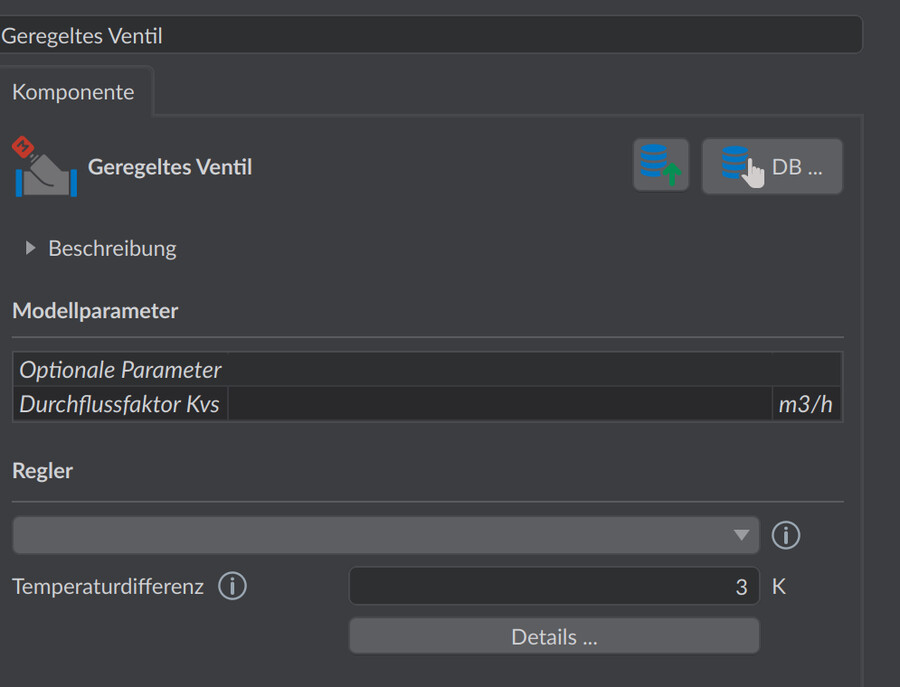
The controlled valve throttles the flow according to the assigned controller. It is the standard valve for flow-rate control at the consumer. Controllable quantities are:
- Mass flux – setpoint mass flux through the branch
- Temperature difference of the following element – e.g. a constant spread across the consumer’s heat exchanger
- Outlet temperature on the secondary side – control to the secondary-side outlet temperature of a transfer station
| Parameter | Unit | Default | Meaning |
|---|---|---|---|
| Kvs value | m³/h | optional | Flow coefficient: volume flow at 1 bar pressure loss in the fully open state |
| Fluid volume | L | 0.5 | Fluid volume of the valve |
If a Kvs value is set, the base pressure loss of the open valve results as
The controller increases the pressure loss beyond this in order to meet the setpoint. Without a Kvs value the valve acts purely as an actuator with no base pressure loss.
Good to know
A set Kvs value makes the controlled valve more realistic: it then already has a base pressure loss in the open state, which the controller only increases further. For pure sizing the ideal actuator without a Kvs value is sufficient; for reliable pressure losses at the consumer, enter the Kvs value from the valve datasheet.
Element, constant pressure loss
An element with a fixed pressure loss independent of the volume flow – for example for a differential pressure controller or a lump-sum built-in component.
| Parameter | Unit | Default | Meaning |
|---|---|---|---|
| Pressure loss | bar | 0.2 | Constant pressure loss (sign follows the flow direction) |
| Fluid volume | L | 0.5 | Fluid volume |
Element, quadratic pressure loss
The pressure loss scales quadratically with the volume flow, defined via a nominal point – the usual model for apparatus whose design pressure loss is known from the datasheet:
| Parameter | Unit | Default | Meaning |
|---|---|---|---|
| Nominal pressure loss | bar | 0.2 | Pressure loss at the nominal volume flow |
| Nominal volume flow | m³/h | 10 | Reference volume flow |
| Fluid volume | L | 1 | Fluid volume |
Element, defined zeta
The pressure loss is computed from a resistance coefficient (zeta value) and the flow velocity – suitable for fittings and built-in components with tabulated zeta values:
| Parameter | Unit | Default | Meaning |
|---|---|---|---|
| Pressure loss coefficient (zeta value) | – | 150 | Resistance coefficient of the element |
| Hydraulic diameter | mm | 50 | Reference diameter for the flow velocity |
| Fluid volume | L | 1 | Fluid volume |
Non-return valve
The non-return valve prevents reverse flow: in the blocking direction the model applies a very high pressure loss, in the flow direction it is resistance-free. The transition is numerically smoothed so that the equation solver remains stable. The valve has no parameters.
Typical application: parallel generators or branches that must not be flowed through in reverse.
Building internal installation
This component represents the pressure loss of the pipe installation in the building – from the house connection to the transfer station – without the lines having to be drawn individually. The pressure loss is computed from the specified pipe length and the configured fittings (e.g. bends); the pipe dimension is automatically taken from the adjacent connection pipe of the network.
| Parameter | Unit | Default | Meaning |
|---|---|---|---|
| Pipe length | m | 20 | Single line length in the building; it is internally doubled for supply and return |
| Fittings | – | – | Number and type of fittings (e.g. bends); the zeta values are summed and likewise applied for supply and return |
The pipe length and fittings of the building internal installation can optionally be counted in the bill of materials.
Notes
- A controller is required only by the controlled valve; all other elements on this page are passive.
- None of these elements support a heat exchange type – they are adiabatic.