Ideal heater/cooler
The ideal heater/cooler: supply temperature via heating curve, prescribed heating power for base-load generators, feed-in profiles and power limits.
Overview
The ideal heater/cooler (ideal heater and cooler) is the standard model of the energy plant: it heats or cools the fluid exactly to the prescribed outlet temperature, without representing a specific generator type (boiler, CHP, …). The predefined simplified energy plant consists of a pump and this generator. A heating curve is required – it provides the supply temperature setpoint as a function of the outdoor temperature.
The model knows two operating modes, which are selected via the heat exchange type.
Operating mode 1: supply temperature control (default)
Without a heat exchange type (setting none) the generator brings the fluid exactly to the supply setpoint of the heating curve. The heating power required for this results from the mass flux and the heating span:
Optionally, maximum heating power and maximum cooling power limit the generation: if the limited power is not sufficient, the outlet temperature remains below the setpoint – this allows generator failures and capacity bottlenecks to be investigated.
Good to know
Via the optional maximum heating power the ideal generator also represents a limited real generator: if the power is not sufficient on cold days, the outlet temperature remains below the setpoint and the undersupply becomes visible in the results. Leave the limit out, and the model always heats exactly to the heating-curve setpoint – ideal for pure network sizing.
Operating mode 2: prescribed heating power
With the heat exchange type constant heating power or time-dependent heating power, the fed-in power is prescribed directly instead – as a fixed value or as a time series. Typical applications:
- Base-load generators with a fixed power (e.g. CHP), while a second generator covers the peak load
- Feed-in profiles from solar thermal or waste heat as a time series
- negative values act as cooling power
In this operating mode the heating curve acts as an upper limit of the supply temperature: the prescribed power is automatically capped so that the outlet temperature does not exceed the heating-curve setpoint – so at a small mass flux, power is not “pushed in” without limit. In addition, the optional power limits apply.
In combination with the controlled pump and the control quantity heating power of the following element, the pump adjusts the mass flux so that the generator can deliver its target power at the supply temperature of the heating curve.
Parameters
| Parameter | Unit | Default | Meaning |
|---|---|---|---|
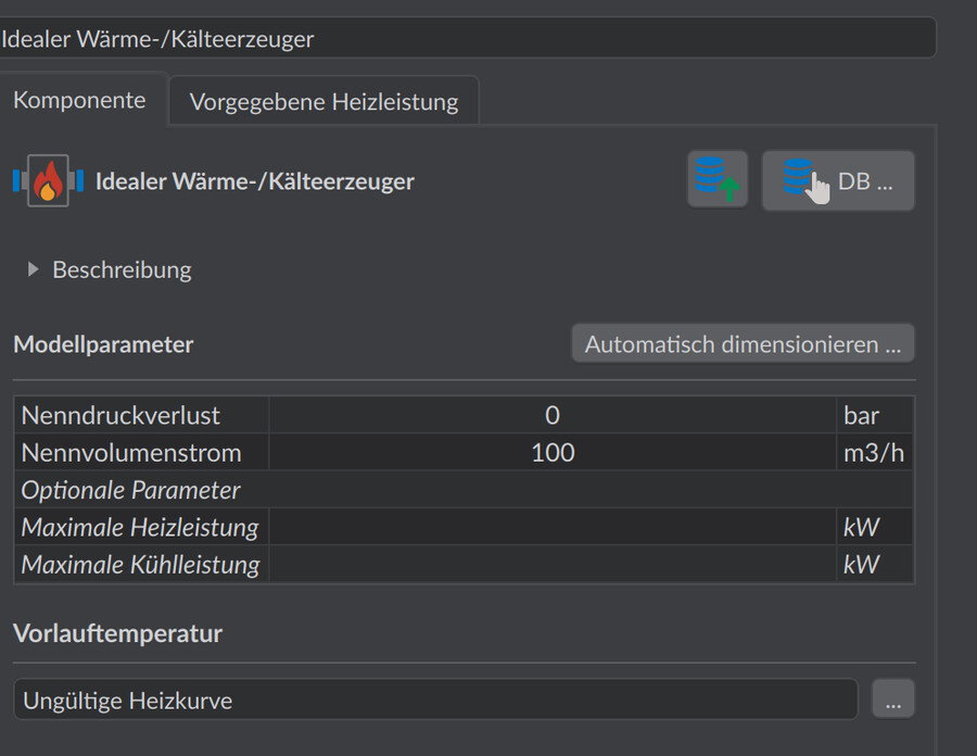
| Nominal volume flow | m³/h | 100 | Reference volume flow for the pressure loss |
| Nominal pressure loss | bar | 0 | Pressure loss at the nominal volume flow; default 0 = pressure-loss-free |
| Maximum heating power | kW | optional | Upper limit of the heating power; unlimited if not specified |
| Maximum cooling power | kW | optional | Upper limit of the cooling power; unlimited if not specified |
Output quantities
| Quantity | Meaning |
|---|---|
| HeatingPower | Heating power fed to the fluid (negative = cooling) |
Since the model knows no efficiency and no fuel, HeatingPower is the basis for downstream evaluations (generation quantities, fuel demand, emissions) – see Line charts.
Notes
- The heating curve of the energy plant is assigned in its settings; a constant supply setpoint can be represented via a constant heating curve.
- Several generators in one plant (e.g. base load with prescribed power + peak load with supply temperature control) are connected in series in the plant editor.