Size & simulate ground heat collectors
Cold district heating, part 6: size ground heat collectors as a heat source and simulate them in the network
Overview
This part shows how a ground heat collector field is sized as a heat source and simulated over two years. Based on the results, it can be assessed whether the system works and whether the minimum temperatures are met.
Replacing the borehole field with a collector
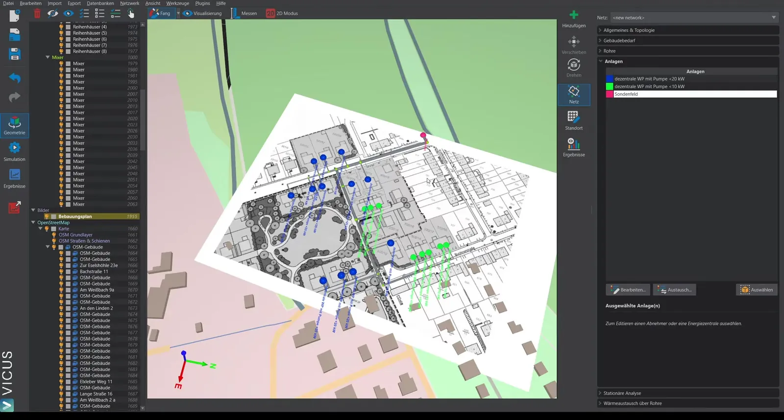
Starting from the example project with a borehole field:
- Open the energy plant in the plant editor.
- Remove the existing borehole field.
- Drag the ground heat collector into the plant.
- Reconnect the elements.
Parameterizing the collector
When you click the collector, the following options are available:
Ground model
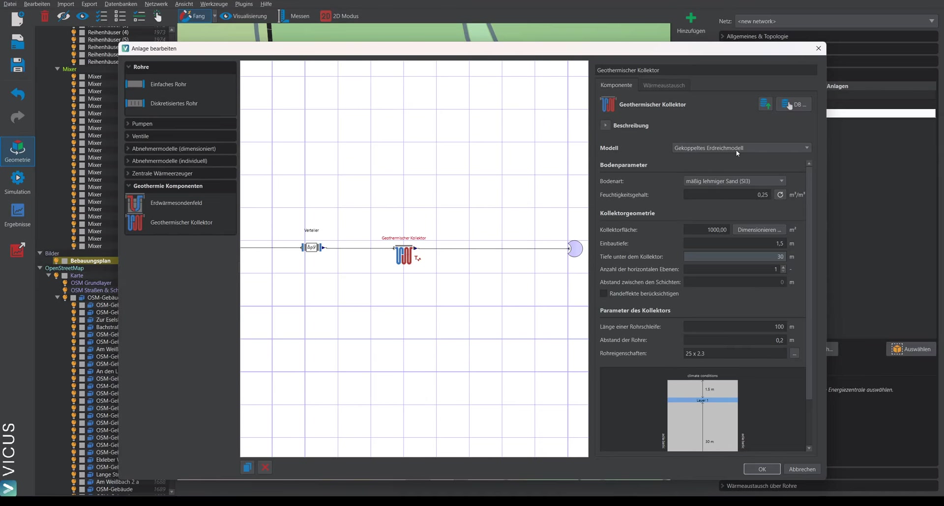
The coupled ground model is selected as the model. A complete geothermal simulation is then carried out in the background. Alternatively, a fixed temperature can be prescribed.
Soil type
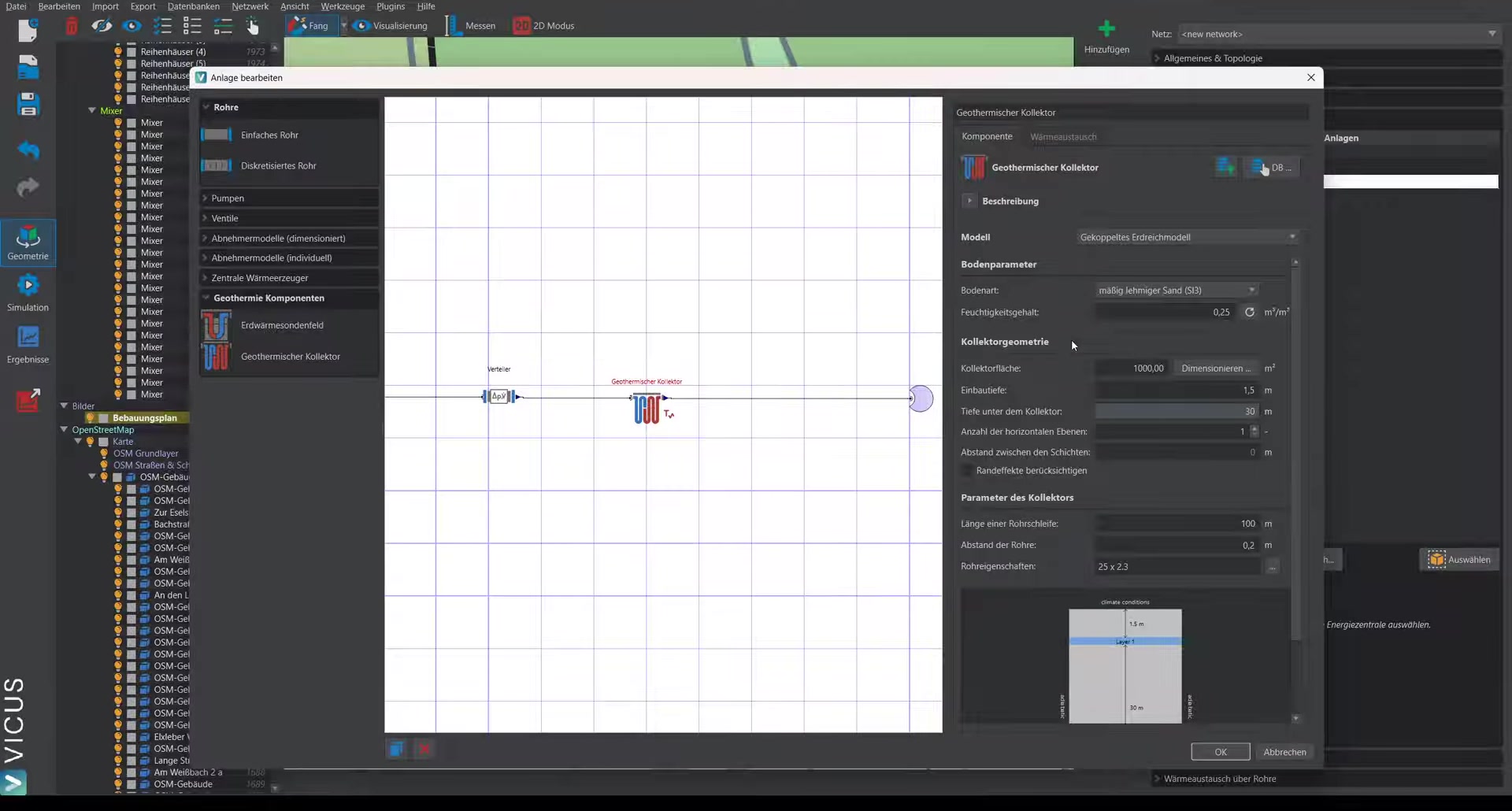
Select the soil type matching the site from the standard soil types. If a soil report is available, the parameters can be set more precisely. For each soil type, a typical moisture content is automatically set that can be adjusted if the actual moisture content is known.
Burial depth and geometry
- Burial depth: e.g. 1.5 m
- Below that, 30 m of ground is co-simulated to ensure undisturbed conditions
- Optional: Two-layer collector (single-layer in this example)
- Optional: account for an edge zone (for the first simulation we recommend simulating without an edge zone; for a more detailed analysis, the collector width and edge-zone width can be specified to run a 2D simulation with additional heat gains from the edge zone)
Pipe loops
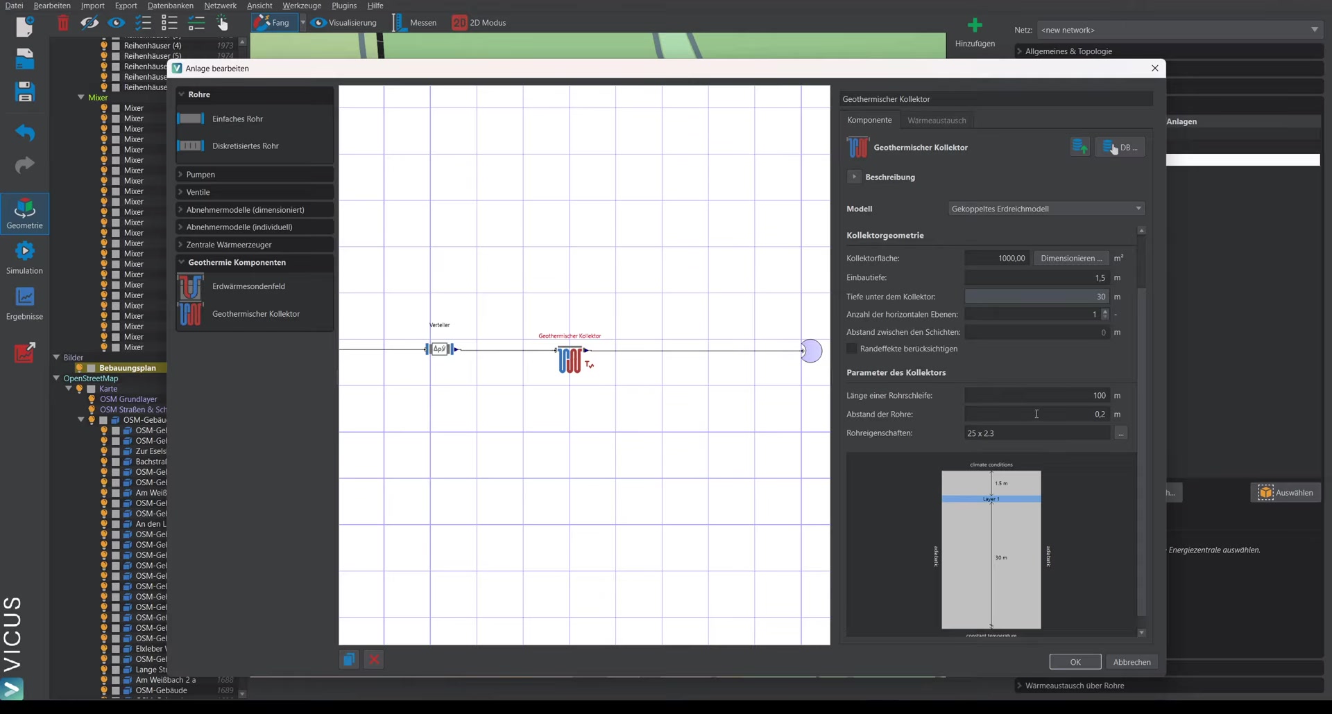
- Pipe dimension: e.g. 25 mm pipe
- Pipe spacing: e.g. 20 cm
- Length per pipe loop: e.g. 100 m (typical length)
The number of parallel pipe loops is automatically calculated to cover the specified collector area.
Sizing the collector area
The collector area must be specified for the simulation. A pre-sizing helper dialog is available for this:
- Click the sizing button.
- The total heat demand of the consumers is determined automatically (e.g. 460 MWh/a).
- A seasonal performance factor is assumed (for pre-sizing only).
- Heat gains of the cold network are estimated (e.g. 120 kWh/m with a 500 m network length).
- The coverage share of the collector is set (e.g. 100 %).
- The estimated collector area is calculated (e.g. 4,490 m²).
Accept the value and start the simulation to verify the result.
Running the simulation
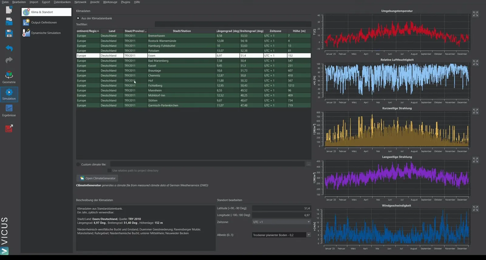
- Confirm the settings.
- Select the climate data file for the site.
- Set the simulation duration to at least 2 years (the first year serves as the settling phase, the second year is evaluated).
- Start the simulation.
Note on runtime: A thermo-hydraulic simulation coupled with a geothermal simulation can take half an hour to an hour or more, depending on project size. With particularly high heat extraction rates, 3 simulation years can also be reasonable.
Evaluating the results
Energy plant (collector field)
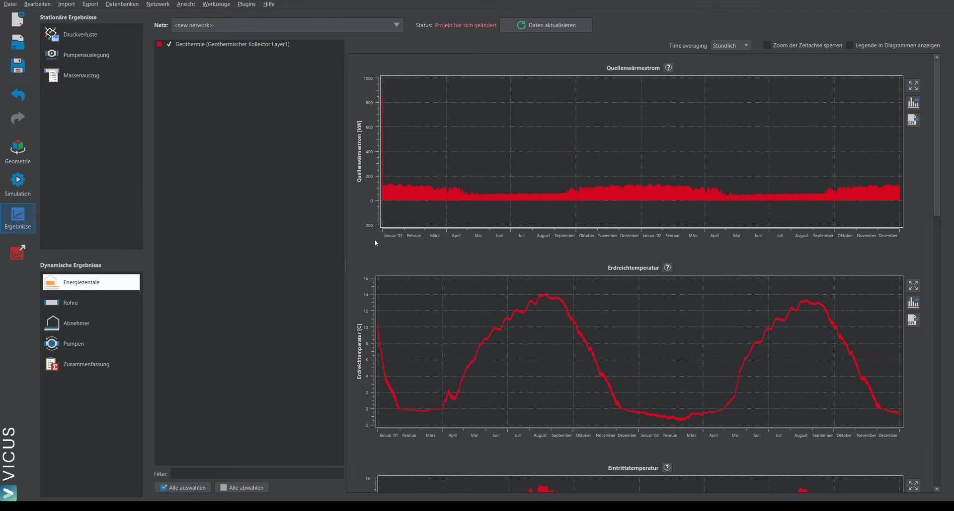
The results of the collector field show:
- Heat gains of the collector field
- Ground temperature: In winter, a horizontal course is visible, caused by ice formation (accounted for in the simulation)
- Inlet and outlet temperatures of the collector field
Checking the consumers
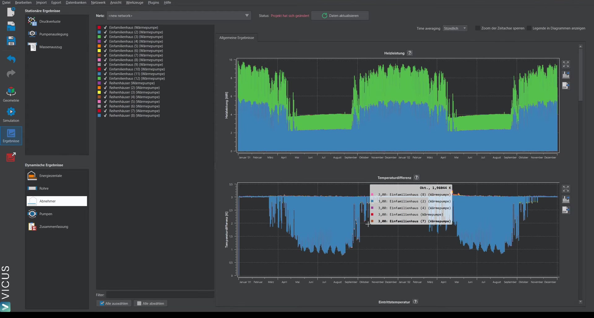
Decisive for evaluating the system are the temperatures at the consumers:
- Temperature difference: Should meet the configured 3 Kelvin (in summer the value fluctuates, as the heat pumps switch off)
- Inlet temperature into the heat pumps: e.g. minimum of approx. -2.6 °C
Based on the minimum inlet temperature, it can be judged whether the system is functional under real-world conditions and whether the collector area has been adequately sized.
Important in practice
The minimum inlet temperature into the heat pumps is the decisive design criterion for the collector field. Even on the coldest design day, it should not fall below the frost limit of the heat pump evaporator. If it drops too far, the collector is too small – enlarge the area or lower the coverage share. A controlled ice-formation effect in the soil is normal in this context and even delivers additional energy via the heat of solidification.