Soil and Ground Temperature in Cold District Heating
Annual ground temperature cycle, the Kusuda model, soil thermal conductivity, burial depth, frost protection and regeneration of uninsulated 5GDHC pipes.
Table of Contents
In cold district heating, the ground acts as heat source, storage and heat exchanger at the same time. At shallow depth its undisturbed temperature follows the annual cycle at the surface: at 1 m depth in central Europe it varies between about 3 °C in February and about 17 °C in August around an annual mean of roughly 10 °C. With increasing depth the amplitude is damped exponentially and delayed in time. How much heat uninsulated pipes and collectors take up is determined by the temperature difference, the thermal conductivity and moisture content of the soil, the burial depth and regeneration in summer.
Undisturbed ground temperature over the year
The undisturbed ground temperature is the soil temperature without the influence of pipes, buildings or heat sources. It is the boundary condition for every calculation of heat gains and losses of buried pipes. Below about 15–20 m it is almost constant and rises slowly with depth according to the geothermal gradient. In the top two metres that matter for networks and collectors, the seasonal cycle dominates.
The Kusuda model
The approach named after Kusuda and Achenbach describes the undisturbed ground temperature using the classical solution of the heat conduction equation for a homogeneous half-space with a periodically varying surface temperature:
where
- is the mean annual ground temperature (in Germany about 9–11 °C, roughly 1–2 K above the mean annual air temperature),
- is the amplitude of the surface temperature,
- is the depth,
- is the period (365 days),
- is the day of minimum surface temperature,
- is the damping depth.
The damping depth depends only on the thermal diffusivity of the soil:
For a typical soil with m²/d (≈ 0.6 · 10⁻⁶ m²/s) this gives m. At depth the amplitude is reduced to 37 % of the surface amplitude and delayed by days.
Amplitude damping and phase shift
The table below evaluates the model for °C, K and m²/d. The values at 1 m depth match the range of about 3–17 °C also used in the article on heat loss calculation.
| Depth | Damping | Amplitude | Range | Time lag |
|---|---|---|---|---|
| 0 m (surface) | 1.00 | ±10.5 K | approx. −0.5 to 20.5 °C | 0 days |
| 0.5 m | 0.81 | ±8.5 K | approx. 1.5 to 18.5 °C | approx. 12 days |
| 1.0 m | 0.66 | ±6.9 K | approx. 3 to 17 °C | approx. 24 days |
| 1.5 m | 0.54 | ±5.6 K | approx. 4.5 to 15.5 °C | approx. 36 days |
| 2.0 m | 0.44 | ±4.6 K | approx. 5.5 to 14.5 °C | approx. 48 days |
| 5.0 m | 0.13 | ±1.3 K | approx. 8.5 to 11.5 °C | approx. 4 months |
| 10 m | 0.02 | ±0.2 K | approx. 10 °C | approx. 8 months |
The phase shift explains why the minimum at 1 m depth occurs in February rather than January, and the maximum only in August. For cold district heating this is favourable: in late winter, when air temperatures are already rising, the ground at pipe depth is at its coldest, whereas at the start of the heating season in autumn it is still comparatively warm.
The model assumes homogeneous soil, a sinusoidal surface temperature and constant material properties. Snow cover, sealed surfaces, shading, groundwater and freezing in winter deviate from this. For site data, national weather services publish measured soil temperatures — in Germany the Deutscher Wetterdienst down to 1 m depth — to which , and can be fitted.
Thermal conductivity and soil moisture
How quickly heat flows towards the pipe is governed by the thermal conductivity . It depends mainly on soil type and water content, because water replaces air in the pores. The guideline VDI 4640 Part 1 gives reference values that lead to the following orders of magnitude:
| Soil type | Thermal conductivity in W/(m·K) |
|---|---|
| Gravel, sand, dry | approx. 0.4 |
| Clay, silt, dry | approx. 0.5 |
| Clay, silt, water-saturated | approx. 1.7 |
| Gravel, sand, water-saturated | approx. 2.4 |
For the design of buried pipes, values of 1.0–2.0 W/(m·K) are commonly used. In the collector and pipe zone, water content and therefore are not constant: in summer the soil near the surface dries out, while precipitation and high groundwater levels increase conductivity. In cold district heating a high conductivity is beneficial — unlike in warm networks — because it improves heat uptake. For design, it is advisable to calculate with a cautious value and check how sensitive the result is to . When pore water freezes, latent heat is released in addition; collectors make deliberate use of this effect.
Heat uptake and release of uninsulated pipes
When the brine temperature is below the ground temperature, heat flows from the soil into the pipe. The heat flow per metre of pipe follows from temperature difference and thermal resistance, as for insulated pipes; without insulation only the resistances of the pipe wall and the soil remain:
The soil resistance of a horizontally buried pipe is given by the EN 13941 formula in the article on heat loss calculation.
Example: PE pipe OD 160 (SDR 11), pipe axis at 1.5 m depth, W/(m·K), W/(m·K). This gives and m·K/W. With a temperature difference of 4 K, the pipe takes up about 8.6 W/m under steady-state conditions. Over a year with an average difference of 3 K, this amounts to about 55 kWh/(m·a) per pipe.
The example is a steady-state approximation with the undisturbed ground temperature as boundary condition. In reality the soil around the pipe cools down, supply and return pipes influence each other, and the ground temperature itself varies through the year. For a twin-pipe route the result is therefore less than twice the single-pipe value. Measurements and simulations of built networks show 50–120 kWh/(m·a) per metre of route for supply and return combined. In summer the heat flow can reverse when cooling waste heat makes the network warmer than the soil; the pipe then releases heat and recharges the ground.
Influence of burial depth
In cold district heating, burial depth works in two directions:
- Shallower (approx. 1 m): the pipe follows the annual cycle more closely. In summer the soil is warmer and regeneration from the surface is faster; in winter it is colder. The soil resistance is lower and the coupling to the surface stronger.
- Deeper (approx. 2 m): the temperature is more damped and higher in winter, but regeneration in summer is delayed and weaker. Excavation, shoring and possibly dewatering become more expensive.
Cold district heating networks are typically laid at 1–2 m depth, horizontal collectors at 1.5–3 m. The optimum depth results from the heat balance, frost safety, the position of other utilities and civil works costs, and is best assessed with an annual simulation for different depths.
Frost risk, brine and glycol
Because the brine temperature can fall below 0 °C in winter, the network is operated with a water–glycol mixture, typically 20–30 vol% monoethylene glycol with frost protection down to about −10 to −15 °C. The brine itself therefore does not freeze. Higher glycol concentrations, however, increase viscosity and pressure loss, and with them pump electricity.
The actual frost issue lies in the soil. With persistently negative brine temperatures, an ice body forms around pipes and collectors. For horizontal collectors, limited freezing is part of the concept because the latent heat of solidification is used. For network pipes under roads, close to buildings or next to drinking water pipes it is undesirable: frost heave can damage surfaces, and neighbouring pipes must not freeze. Permissible brine temperatures therefore have to be defined for each project and verified over a multi-year period. For borehole heat exchangers, VDI 4640 Part 2 specifies limits for the brine temperature.
Regeneration in summer
The heat that the network extracts in winter has to flow back on an annual average. Three mechanisms contribute:
- Surface input: solar radiation, warm air and precipitation heat the ground from above. For collectors and network pipes at 1–2 m depth this is the most important source.
- Cooling: buildings cooled via the network in summer feed heat in. In districts with non-residential use this can preheat the ground considerably (see prosumers).
- Lateral heat flow: for deep borehole heat exchangers, regeneration takes place mainly through heat conduction from the surrounding rock and is correspondingly slow.
If regeneration is insufficient, the ground temperature falls from year to year until a new, lower equilibrium is reached. The source temperature, and with it the seasonal performance factor of the heat pumps, decreases. This is why the design is checked over several years of operation.
Ground model in VICUS Districts
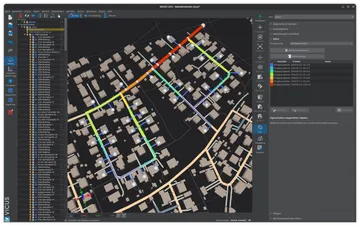
A detailed ground model is calculated coupled with the network simulation. The soil is spatially discretized along the route, so that local ground temperatures, seasonal fluctuations and the influence of neighbouring pipes are captured dynamically. For cold district heating the model calculates the network’s heat gains from the ground and represents the long-term thermal depletion of the soil over several years of operation. Borehole heat exchangers and horizontal ground collectors are simulated with the same coupled ground model.
The ground as a design parameter
The undisturbed ground temperature provides the boundary condition, thermal conductivity and moisture of the soil determine the heat flow, and burial depth and regeneration decide whether the system remains stable over the years. Analytical approaches such as the Kusuda model and the steady-state resistance formulas are suitable for plausibility checks. Designing network and source requires coupled, transient multi-year calculations, because ground, network and heat pumps influence each other.
Further reading: Dimensioning 5GDHC Networks — ground coupling and annual balance in the context of network design, Heat Loss Calculation — thermal resistances of buried pipes according to EN 13941, Cold District Heating: Costs — how ground properties determine the cost of heat sources.
References and Standards
- Kusuda, T.; Achenbach, P. R. (1965): Earth Temperature and Thermal Diffusivity at Selected Stations in the United States. ASHRAE Transactions, 71(1), pp. 61–75.
- Carslaw, H. S.; Jaeger, J. C. (1959): Conduction of Heat in Solids. 2nd ed., Oxford University Press.
- VDI 4640 Part 1 — Thermal use of the underground — Fundamentals, approvals, environmental aspects
- VDI 4640 Part 2 — Thermal use of the underground — Ground source heat pump systems
- EN 13941 — District heating pipes — Design and installation of thermal insulated bonded single and twin pipe systems
- Deutscher Wetterdienst: Soil temperatures at DWD stations, Climate Data Center (opendata.dwd.de).
- Bertermann, D.; Wienke, J.; Müller, J.; Böck, S.; Lach, G.; Steinhäuser, H. (2019): Oberflächennahste Geothermiesysteme als Quelle für kalte Nahwärmenetze. bbr — Leitungsbau, Brunnenbau, Geothermie, pp. 62–65.
- Hirsch, H.; Nicolai, A. (2022): An efficient numerical solution method for detailed modelling of large 5th generation district heating and cooling networks. Energy, 255, 124485.
- Hirsch, H. (2024): Modelling of Fifth Generation District Heating and Cooling Networks Coupled to Ground Heat Exchangers. PhD thesis, TU Dresden.
Frequently Asked Questions
What is the ground temperature at a depth of 1 to 2 m?
How much heat does an uninsulated pipe take up from the ground?
Can a cold district heating network freeze?
What does ground regeneration mean?
Related Articles
Cold district heating (5GDHC) explained: operating principle, heat sources, decentralized heat pumps and network hydraulics of 5th-generation networks.
5GDHC simulation and dimensioning of cold district heating networks: passive vs. active networks, pressure-loss criteria and ground coupling.
How do prosumer concepts work in district heating networks? Heat feed-in, bidirectional networks and operating models
Advantages and disadvantages of cold district heating (5GDHC): under 3 % heat losses and free cooling versus decentralized heat pumps and more complex planning.
Disclaimer: The content of this page is for general information purposes only and does not constitute legal, planning or engineering advice. All information is provided without guarantee. Despite careful research, VICUS Software GmbH assumes no liability for the accuracy, completeness or timeliness of the information provided. Third-party product names and trademarks are mentioned for informational purposes only and are the property of their respective owners.