Network Topology and Structure
Thermal network topology: pipe hierarchy, radial, ring, and meshed networks compared. System variants and selection criteria for planning.
Table of Contents
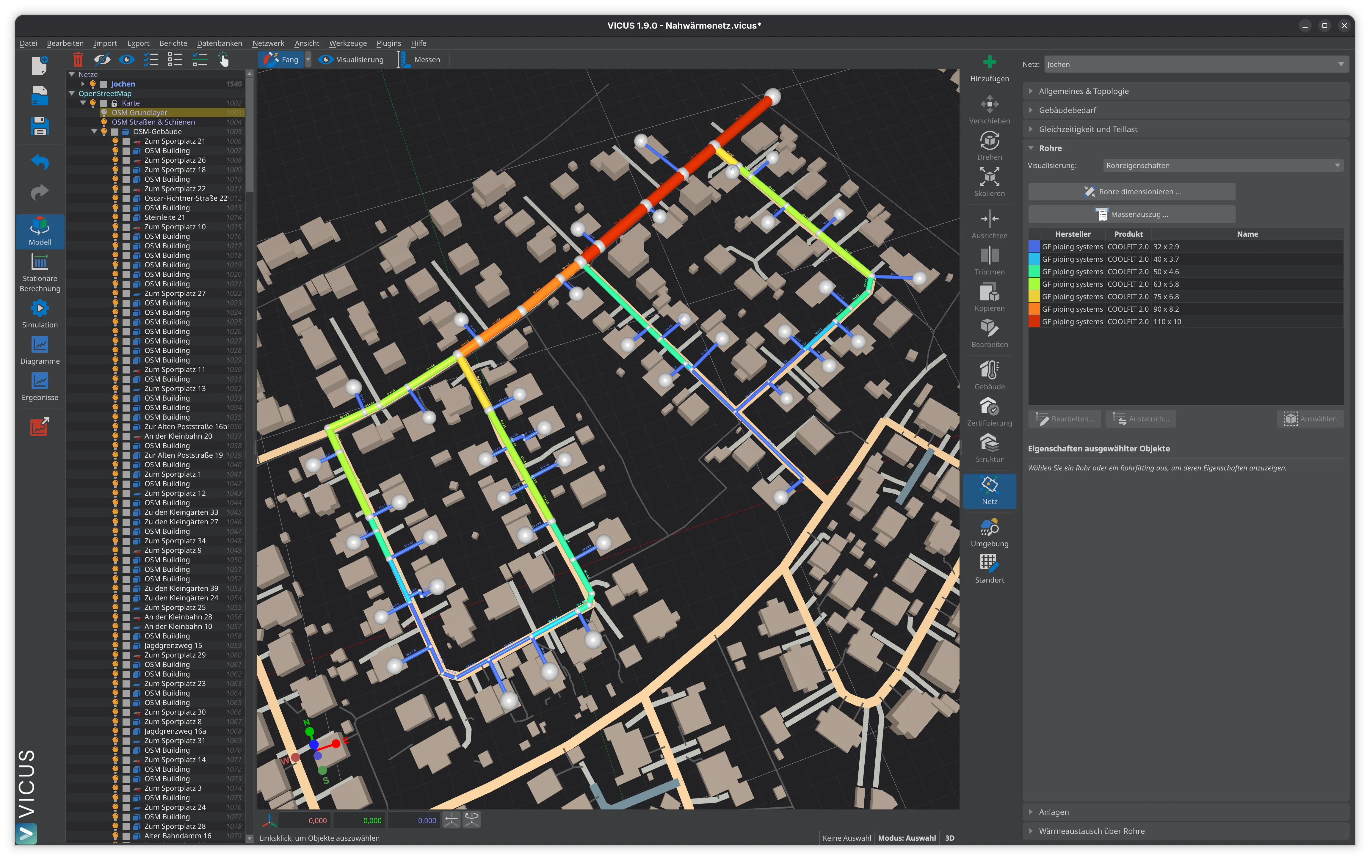
The topology of a thermal network is organised into three pipe hierarchy levels, transmission, distribution and service connections, and it can be laid out as a radial, ring or meshed network. The two-pipe system with a supply and a return line is the standard; three-pipe systems come into play where space heating and domestic hot water need different temperature levels. Choosing the network structure is an early planning decision that fixes supply security, heat losses, investment costs and the long-term expandability of the whole system.
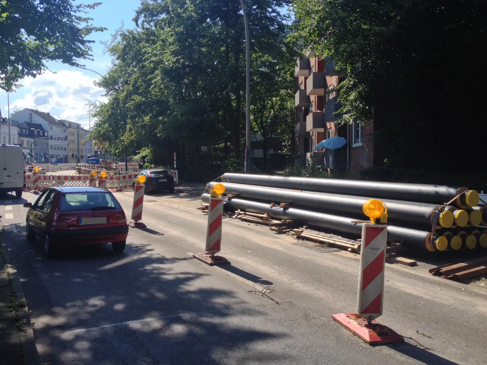
Photo: Cvoelker · CC BY 4.0 · via Wikimedia Commons
Pipe Hierarchy
A thermal network is typically organised into three hierarchical pipe levels. The transmission and trunk line connects the energy centre with the supply areas; here the nominal diameters and volume flow rates are largest, and the line bridges long distances at the lowest possible pressure loss. The distribution line branches off from the trunk line to serve individual streets or neighbourhoods, its nominal diameters shrinking with distance from the trunk. The service connection links the distribution line to the transfer station in the building, has the smallest nominal diameters and usually runs as a single line per building.
This subdivision carries over into the hydraulic calculation. Transmission lines largely set the overall pressure loss of the network, whereas service connections mainly govern the differential pressure available at the transfer station.
Classification by Number of Pipes
Two-Pipe System
The two-pipe system is the standard for modern thermal networks. A supply line and a return line form a closed circuit. The heat transfer medium, usually water, is heated in the energy centre, travels to the customers through the supply line, releases heat at the transfer station and returns to the centre through the return line. The design is simple and inexpensive, the control technology well proven and the installation costs low. Virtually all heating networks planned and operated today rest on the two-pipe system.
Three-Pipe System
The three-pipe system adds one line to the two-pipe arrangement, in one of two common variants. With two supply lines and one return, one supply line runs at a variable temperature for weather-dependent consumers (space heating) and the other at a constant temperature for weather-independent consumers (domestic hot water, process heat). With one supply and two return lines, the return is split by temperature level to give certain generators, heat pumps for instance, the lowest possible return temperature.
The payoff is demand-responsive control of different consumer groups, lower heat losses in the variable-temperature line during mild weather and better integration of low-temperature heat sources. Against that stand higher investment costs for the third line, more complex control and operation, and a greater space requirement in the trench.
Four-Pipe System
The four-pipe system consists of two separate two-pipe circuits. It serves two typical purposes: heating and cooling, with one circuit for heat and a second for cooling in areas that need both at once; or different temperature levels, with a high-temperature circuit for process heat and a low-temperature circuit for space heating. High investment costs and a large space requirement keep the four-pipe system rare, reserved for specific requirements.
Network Structures
Radial Network
The radial network (also branched or tree network) is the simplest structure. From a single feed-in point, the energy centre, pipelines branch out in a star pattern and subdivide into ever smaller branches, with nominal diameters decreasing towards the periphery. The structure is clear, the investment costs are low and the hydraulic conditions are unambiguous. The price is a lack of redundancy: if a pipe fails, every customer downstream loses supply. Extending the endpoints later forces larger nominal diameters onto the existing pipelines, and the critical point always sits at the most remote end of the branch. A radial network suits smaller networks with a manageable number of customers and modest supply security requirements.
Ring Network
The ring network is a special case of the meshed network in which a closed ring line supplies the connected customers, with feed-in at one or more points on the ring. If a pipe fails, most customers keep their supply through the alternative route, the pressure conditions across the network are more uniform, and additional feed-in points integrate more easily. The trade-off is higher investment costs than a radial network and a more involved hydraulic calculation. Ring closure is often carried out in a later expansion phase, once supply security has to be raised.
Meshed Network
The meshed network arises when several energy centres are interconnected by meshed pipelines in combined operation. It is the most complex structure and also the most supply-secure. Multiple feed-in points and redundant pipeline routes give the highest supply security, various generation plants can be deployed flexibly depending on the load case, and the network expands well. Set against this are high investment costs and the complexity of the hydraulic calculation, the operation and the control of the feed-in points. Meshed networks are usually the product of continuous expansion over many years and are found mainly in larger urban district heating systems.
Sub-Distribution and Route Alignment
How the distribution line reaches the individual buildings is a question of route alignment, and four basic variants are distinguished. In standard route alignment, each building has its own service connection to the distribution line; this is the most common and most flexible variant. Building-to-building alignment groups several buildings on a shared spur that runs from one to the next, which shortens the total route but ties the buildings together. Loop-in alignment routes the distribution line straight through the buildings and is rarely used, mainly with flexible pipe systems (PMR). Basement routing runs the distribution line through the basements of the connected buildings, which lowers burial costs but requires wall penetrations and agreements with the owners.
Evolution of Network Structure
The structure of a thermal network typically evolves through four stages over years or decades:
- Individual radial networks: during the development phase, independent radial networks grow around individual energy centres, each supplying its own defined supply area.
- Interconnection: neighbouring radial networks are joined by tie lines, which balances load between the centres and raises supply security.
- Ring closure: targeted tie lines close open branches into rings, creating alternative supply routes and improving pressure conditions.
- Meshed network: continued extensions and ring closures produce a meshed network with multiple feed-in points and redundant routes.
This progression is characteristic of many urban district heating systems and mirrors the growing weight of supply security as customer numbers rise.
Choosing the network structure
The network structure is a central planning decision that sets the investment costs, supply security and long-term expandability of a thermal network. Radial networks are a good way into piped heat supply, while ring and meshed networks provide the redundancy that larger supply areas need. The hydraulic effects of different structures and route alignments can be examined and optimised in detail with simulation software such as VICUS Districts.
Further reading: Pipe Dimensioning describes how the nominal diameters of the individual pipe hierarchy levels are calculated, Supply Area and Heat Demand Density explains the delineation and evaluation of supply areas as the basis for the network structure, and Planning Phases for Thermal Networks places the network structure decision within the overall planning process.
References and Standards
- AGFW FW 401 — Installation and Statics of Pre-insulated Bonded Pipes in District Heating Networks
- Nussbaumer, T.; Thalmann, S.; Zaugg, D.; Cueni, M. (2025): Planungshandbuch Thermische Netze. Version 2.0, EnergieSchweiz / Bundesamt fuer Energie BFE.
- AGFW FW 440 — Hydraulic Calculation of Hot Water District Heating Networks
Frequently Asked Questions
What are the network topologies for district heating?
What is the difference between a two-pipe and a three-pipe system?
What types of service connection routing exist in thermal networks?
Related Articles
Overview and comparison of pipe systems for thermal networks: KMR, MMR, PMR, PE pipes, ductile cast iron, GRP, and SMR
Open-trench and trenchless installation of district heating pipes: route planning, trench profiles, bedding and the cost share of civil works in network projects.
Thermal expansion and stress in district heating pipes: calculation formulas, cold installation, pre-stressing and expansion compensation — explained with worked examples.
Disclaimer: The content of this page is for general information purposes only and does not constitute legal, planning or engineering advice. All information is provided without guarantee. Despite careful research, VICUS Software GmbH assumes no liability for the accuracy, completeness or timeliness of the information provided. Third-party product names and trademarks are mentioned for informational purposes only and are the property of their respective owners.