Pipe Statics: Thermal Expansion & Stress
Thermal expansion and stress in district heating pipes: calculation formulas, cold installation, pre-stressing and expansion compensation — explained with worked examples.
Table of Contents
A steel pipe in district heating networks expands by about 1.2 mm per metre per 100 K temperature difference, and for unalloyed steel the yield strength is already exceeded at roughly 62 K of fully restrained expansion. Three installation methods keep this in check: cold installation with natural anchor points (up to approx. 85 degC), operational self-pre-stressing through controlled plastic compression (up to approx. 120 degC), and thermal pre-stressing, which halves the maximum axial stress. Pipe statics assesses these loads and sets the design criteria that govern the installation method, the anchor point spacing and the expansion measures.
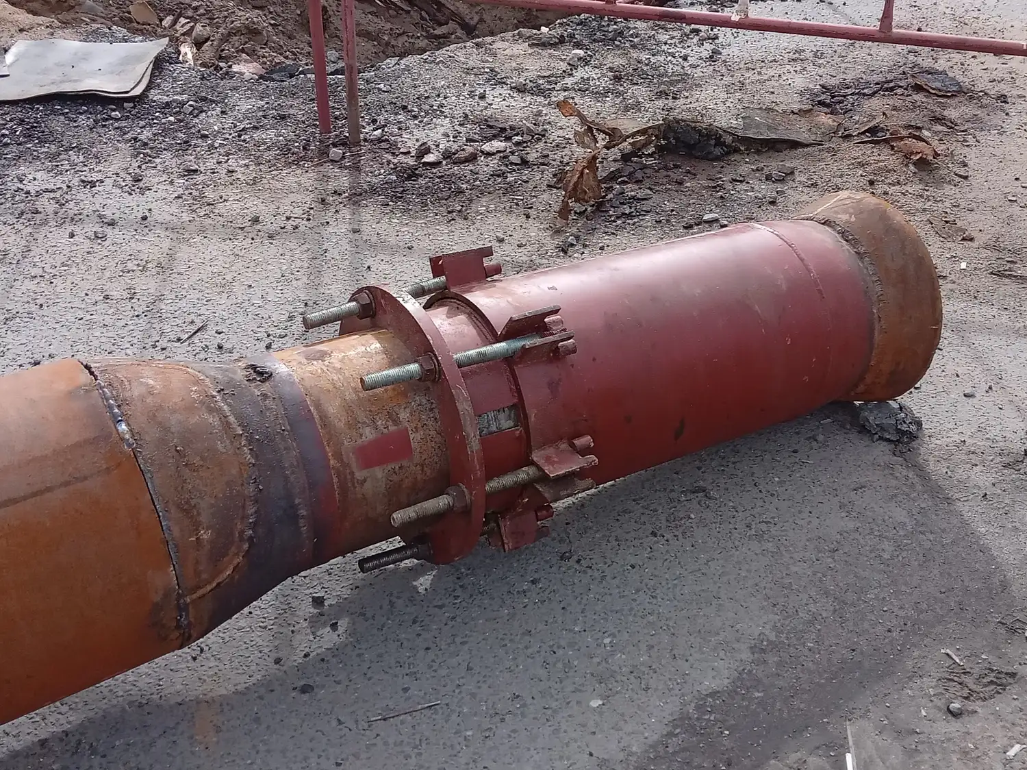
Photo: Georg Pik · CC0 · via Wikimedia Commons
Pressure Resistance and Wall Thickness
The minimum wall thickness of a pressure pipe is derived from the so-called boiler formula. For a cylindrical pipe under internal pressure , the required failure wall thickness is:
Here, is the pipe outer diameter and is the allowable stress of the material. The allowable stress is derived from the yield strength or the tensile strength , taking into account safety factors:
The safety factors according to the code are (against yielding) and (against rupture). The ordered wall thickness must exceed the calculated wall thickness including manufacturing tolerances and corrosion allowances:
where is the manufacturing allowance and is the corrosion and wear allowance.
Thermal Expansion and Thermal Stress
When a pipe of length is heated by a temperature difference , its length changes by:
The linear thermal expansion coefficient and the modulus of elasticity depend on the material. The following table provides reference values for the materials commonly used in heating networks:
| Material | (10/K) | (kN/mm) |
|---|---|---|
| Steel, unalloyed | 12.0 | 210 |
| Steel, high-alloy (austenitic) | 16.7 | 200 |
| Copper | 16.5 | 100 — 130 |
| Aluminium | 23.0 | 70 |
| Grey cast iron | 9.0 | 90 — 145 |
If the pipe cannot expand freely — for example between two anchor points — a thermally induced axial stress arises:
From the condition , the maximum permissible temperature difference under fully restrained expansion follows:
For unalloyed steel with N/mm, this yields K — a value that is regularly exceeded in high-temperature networks. Without expansion measures, the yield strength would be exceeded.
Design Temperature for Pipe Statics
The pipe statics temperature difference determines the stresses and forces used in the design:
is the design temperature and is the installation temperature. The following recommendations apply to both.
For the design temperature : buried pipes with an operating temperature 100 degC are designed for 110 degC; buried pipes above 100 degC for 130 degC, but at least 10 degC above the maximum operating temperature; above-ground pipes for 10 degC above the maximum operating temperature.
For the installation temperature : summer installation is taken as 20 degC, spring or autumn as 10 degC, winter as 0 degC. Above-ground pipelines are generally assumed at 20 degC, the most unfavourable load case during summer cooling.
The installation temperature defines the stress-free state. The lower it is set, the higher becomes, and with it the calculated load.
Expansion Accommodation
Thermal elongation in heating networks is preferably taken up by natural compensation through changes of direction in the route. Three basic configurations are common. The L-bend is a single 90 deg change of direction; its expansion capacity is comparatively low, since only one leg deflects elastically, so it suits short pipeline sections with moderate temperature differences. The Z-bend uses two opposing 90 deg changes to form an offset, offers more capacity than the L-bend and is often chosen where the route needs an offset anyway. The U-bend places two 90 deg bends in the same direction to form a loop; it is the most flexible and is used on long straight runs with no natural change of direction.
The 90 deg bend is optimal because it absorbs the expansion of both legs. Larger angles increase the expansion range and can help in confined spaces, while angles below 90 deg are not recommended, as the expansion capacity falls off sharply.
Installation Methods for Buried KMR Pipes
Cold Installation — Method 1: Natural Anchor Points
In Method 1, the pipe is installed in the cold state and the trench is backfilled immediately. Friction between the casing pipe and the soil forms natural anchor points (NAP) that fix the pipe in sections. Thermal expansion is entirely accommodated by bends and changes of direction. This method is permissible up to a maximum operating temperature of approximately 85 degC and is suitable for low-temperature networks with moderate temperature differences.
Cold Installation — Method 2: Operational Self-Pre-Stressing
In Method 2, the pipe is also installed cold and backfilled immediately. During the first heat-up, the axial stress exceeds the yield strength of the steel ( = 235 N/mm for S235). A controlled plastic compression occurs, which permanently pre-stresses the pipe. The maximum installation length between two expansion elements is specified by the manufacturer and must not be exceeded.
Method 2 is more cost-effective than Method 1 but is subject to restrictions: mitre welds on fittings are not permitted, hot tapping on pre-stressed sections must not be performed, and the system must be approved for plastic loading. This method is commonly applied in conventional district heating networks with operating temperatures up to approximately 120 degC.
Thermal Pre-Stressing
In thermal pre-stressing, the pipes are heated to a pre-stressing temperature before the trench is backfilled. This allows them to expand freely in the open trench. Only after the pre-stressing temperature is reached is the trench backfilled and the pipe fixed. The pre-stressing temperature is approximately half the pipe statics temperature difference plus the installation temperature:
The advantage: the maximum axial stress during operation is halved, since the pipe moves within a symmetrical range during both heating (compressive stress) and cooling (tensile stress). There is no limitation on installation length and no restrictions regarding hot tapping or fittings. Thermal pre-stressing is the most flexible but also the most elaborate method, as a mobile heating unit and careful temperature monitoring are required.
Plastic Pipes
Plastic medium pipes (PMR) made of PEX or PB behave quite differently from steel pipes. The thermal expansion coefficient of PE, at roughly K, is about 17 times that of steel, while the modulus of elasticity is many times lower. In buried systems, soil pressure on the casing restrains almost all of the expansion. The pipe is effectively self-compensating, because the low stiffness of the plastic generates only minor stresses.
For above-ground PMR pipes, this soil pressure compensation is absent. Here, anchor points must be set before bends and at branches to prevent uncontrolled movements and forces on connections.
Choosing the installation method
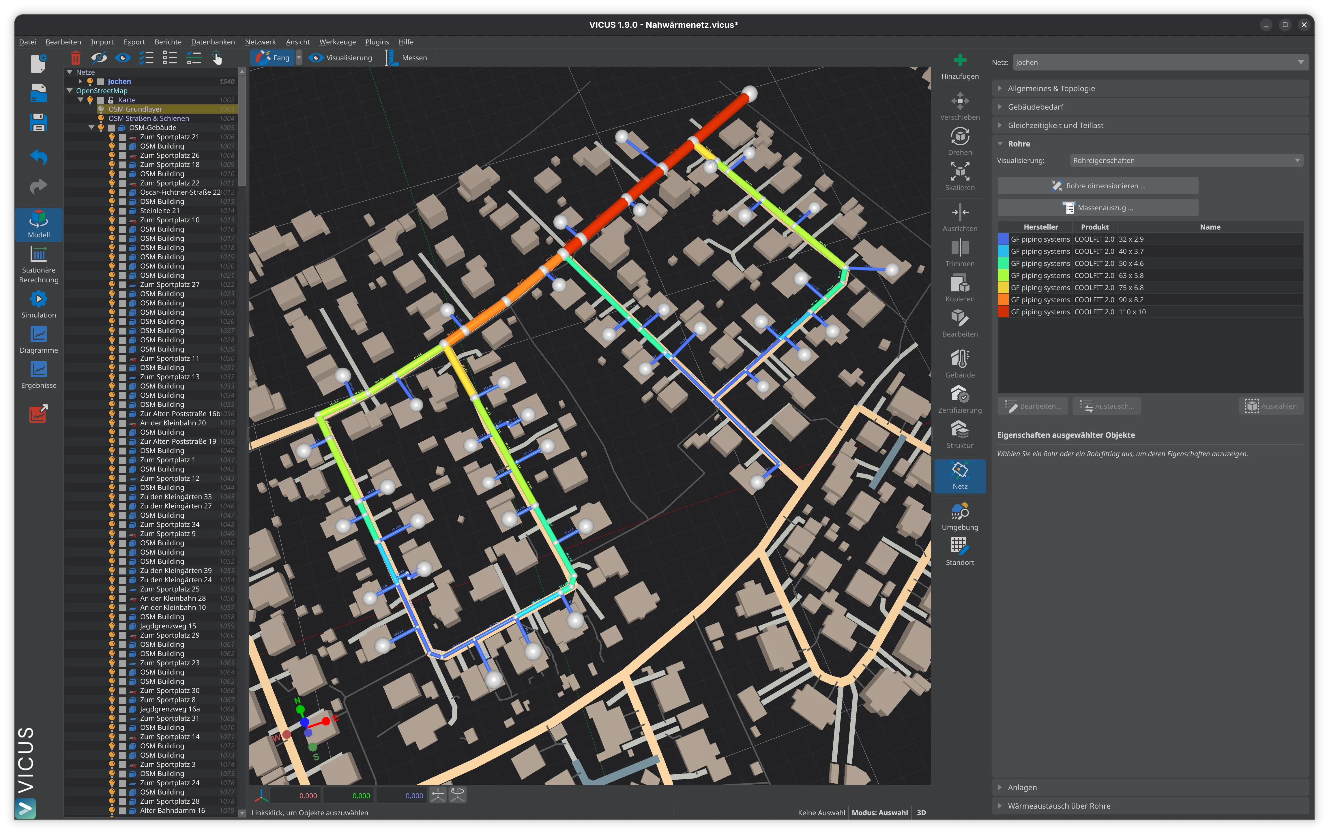
Pipe statics ties material mechanics to the actual installation situation on site. Thermal expansion drives the stresses and forces, and in the end the choice of installation method. Cold installation with natural anchor points is the simplest solution, but only for moderate temperatures. Operational self-pre-stressing widens the range of application at the price of restrictions on fittings and hot tapping. Thermal pre-stressing is the most flexible, though it demands the most effort on site. In every case, a careful calculation of temperature differences, stresses and anchor point spacings is essential. Simulation tools such as VICUS Districts support this work with integrated thermo-hydraulic and pipe statics analysis.
Further reading: Pipe Systems Compared compares the material properties and expansion characteristics of the various pipe systems, Pipe Dimensioning covers the determination of nominal diameters and wall thicknesses, and Network Temperatures explains the operating temperatures that serve as the design basis for pipe statics calculations.
References and Standards
- AGFW FW 401 Part 10 — Installation and Statics of KMR — Fundamentals of Pipe Statics Design
- DIN EN 13941 — District Heating Pipes — Design and Installation of Factory-insulated Bonded Pipe Systems
- AGFW FW 401 — Installation and Statics of Pre-insulated Bonded Pipes in District Heating Networks
Frequently Asked Questions
How much does a steel pipe expand in district heating networks?
What is the difference between cold installation and thermal pre-stressing?
What expansion configurations are used in heating networks?
Related Articles
Overview and comparison of pipe systems for thermal networks: KMR, MMR, PMR, PE pipes, ductile cast iron, GRP, and SMR
Thermal network topology: pipe hierarchy, radial, ring, and meshed networks compared. System variants and selection criteria for planning.
Open-trench and trenchless installation of district heating pipes: route planning, trench profiles, bedding and the cost share of civil works in network projects.
Disclaimer: The content of this page is for general information purposes only and does not constitute legal, planning or engineering advice. All information is provided without guarantee. Despite careful research, VICUS Software GmbH assumes no liability for the accuracy, completeness or timeliness of the information provided. Third-party product names and trademarks are mentioned for informational purposes only and are the property of their respective owners.