Sizing Heat Transfer Stations in District Heating
How to size house transfer stations: domestic hot water priority, space heating loads and diversity factors — with sizing guidance for district heating connections.
Table of Contents
A heat transfer station (HTS) passes the network heat to the building-side heating circuits and domestic hot water preparation, usually through a plate heat exchanger with approach temperatures of 2—5 K. Dimensioning rests on the heat load for space heating and DHW, and on diversity factors that can cut the DHW peak load to just 10—18 % of the sum of individual loads across 100 dwelling units. An undersized station falls short of demand on cold days; an oversized one drives up investment costs and return temperatures.
Structure and components
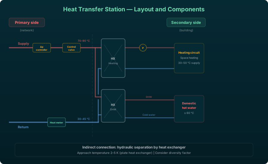
A typical house transfer station is built from a handful of core components. The primary-side connection carries shut-off valves, a strainer and a differential pressure controller. A heat exchanger provides the hydraulic separation between network and building for an indirect connection. A control valve with actuator sets the primary-side flow rate, and a heat meter records consumption. On the secondary side sit the circulation pump, the safety group and the expansion vessel.
Hydraulic separation through a plate heat exchanger is standard in most networks, because it shields the network from pressurization issues and permits different operating pressures on the primary and secondary sides.
Transfer stations in VICUS Districts:
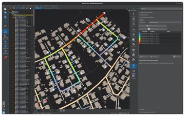
Transfer stations are modelled as network components in four variants: heat exchanger with individual characteristic values, generic heat exchanger (sized automatically from the connection load), district heating transfer station with limited capacity, and generic district heating transfer station (sized automatically). The “generic” variants derive their thermal capacity directly from the building connection load — manual sizing is not required. Primary and secondary side temperatures are calculated separately, so supply and return temperatures on both sides are available as simulation results.
Required differential pressure
For a transfer station to reach its design output, a minimum differential pressure between supply and return has to be available on the primary side. It is typically 0.5 to 1.0 bar; 0.8 to 1.0 bar has become established as the planning value. The technical connection requirements (TAB) of the network operator are binding in every case and may set the value differently for each pressure zone. The derivation is given in Meeting Operating Pressure Limits in Heat Networks.
Available network differential pressure versus the demand of the station
The two quantities have to be kept apart. The available differential pressure is a network quantity: it follows from the pump head minus the friction losses in supply and return up to the transfer point, and is smallest at the index point. The required differential pressure is a plant quantity and follows from how the station is built:
- Control valve with sufficient valve authority — this share dominates the sum. If too little differential pressure drops across the valve, the control works only in the upper part of the stroke and tends to hunt.
- Primary-side pressure loss of the heat exchanger at design output.
- Strainer, shut-off valves and heat meter.
- House connection line from the route into the station, there and back.
What has to be checked is that the available differential pressure reaches the required one at every transfer point — in the least favourable operating case, not on average. Too little differential pressure means the station can no longer reach its output; too much means noise and valve wear, and has to be dissipated through hydraulic balancing. Network operators therefore often specify a maximum differential pressure alongside the minimum.
The pressure rating of the station as a limit of its own
The pressure rating of the station is a separate matter from the required differential pressure. Heat exchangers, control valves, strainers and heat meters carry permissible operating pressures of their own, frequently below the nominal pressure rating of the installed pipe system. For the maximum permissible operating pressure, however, it is always the weakest component on the path under consideration that counts. A transfer station therefore sets an MOP limit in its own right, even where the pipes would allow a higher rating — and that limit also has to withstand the rest pressure of the network and the test pressure of the leak-tightness test.
Domestic hot water preparation
In many cases the domestic hot water (DHW) preparation sets the peak output of the transfer station and therefore its dimensioning. Two basic systems are distinguished.
Indirect preparation with storage tank
A DHW storage tank, typically 200 to 500 litres for single-family houses and 500 to 2000 litres for multi-family houses, is charged from the network through a heat exchanger. The required charging power depends on the chosen charging time and the storage volume:
with the storage volume , the density , the specific heat capacity , the temperature difference (typically 45 K when heating from 10 to 55 °C) and the charging time .
The advantage of a storage system is its lower connection power: the tank can be charged over a longer period, say 2 to 4 hours, so the network peak output stays lower. The drawback is the legionella risk at storage temperatures below 60 °C, which calls for regular thermal disinfection.
Direct preparation (instantaneous principle)
In a fresh water station, the drinking water is heated in flow-through mode through a plate heat exchanger. Because no hot drinking water is stored, the legionella risk practically disappears. In return, this variant needs a much higher peak output, since the entire tap demand must be met in real time.
For a single-family house with a peak tap demand of about 15 l/min at 45 °C and a cold water temperature of 10 °C, this yields:
This value shows why diversity factors matter so much in network sizing: not all buildings tap at full heat load at the same moment.
Diversity factors
The diversity factor describes the ratio of the actually simultaneously occurring output to the sum of all installed connection loads:
Diversity decreases as the number of consumers increases, since individual demand peaks fall at different times. In practice, space heating diversity and DHW diversity are treated separately.
Space heating diversity
Diversity for space heating is comparatively high, since all buildings heat simultaneously at low outdoor temperatures. Typical values:
| Number of consumers | |
|---|---|
| 1-5 | 1.0 |
| 10 | 0.85 - 0.95 |
| 50 | 0.75 - 0.85 |
| 100 | 0.70 - 0.80 |
DHW diversity
DHW diversity is significantly lower, since tapping events are short and statistically distributed:
| Number of dwelling units | (instantaneous) |
|---|---|
| 1 | 1.0 |
| 10 | 0.40 - 0.50 |
| 50 | 0.15 - 0.25 |
| 100 | 0.10 - 0.18 |
| 500 | 0.05 - 0.10 |
These values draw on DIN 4708 and on empirical data from the operation of existing networks. For buildings with storage-tank systems, DHW diversity at network level largely disappears, since the tanks can be charged asynchronously.
Sizing for different building types
Single-family house (new build, KfW-55 standard)
- Heat load: 4 to 6 kW
- DHW output (instantaneous): 30 to 40 kW
- DHW output (storage, 300 l): 8 to 12 kW
- Typical connection load: 15 to 20 kW (with storage)
Multi-family house (20 dwelling units, existing building)
- Heat load: 80 to 120 kW
- DHW output (central fresh water station): approx. 120 kW
- DHW diversity factor: approx. 0.35
- Typical connection load: 120 to 160 kW
Commercial building (office, 2000 m)
- Heat load: 60 to 100 kW
- DHW output: low (5 to 10 kW)
- Typical connection load: 70 to 110 kW
Supply temperature and approach temperature
The required primary-side supply temperature depends on the secondary-side requirements plus the approach temperature of the heat exchanger. The approach temperature is the minimum temperature difference between the primary and secondary sides:
For plate heat exchangers in transfer stations, typical approach temperatures lie between 2 and 5 K. DHW preparation to 55 °C with a 3 K approach therefore calls for a primary supply temperature of at least 58 °C.
The return temperature likewise has a strong bearing on network efficiency. Return temperatures below 40 °C reduce heat losses and widen the usable temperature spread; see return temperatures. On the primary side, the secondary return temperature is undercut by the approach temperature:
Buffer storage on the network side
In some network concepts, a central or decentralised thermal energy storage tank on the primary side smooths out load peaks. Its size depends on the expected peak output and the desired bridging time:
For a peak output of 500 kW, a bridging time of 30 minutes and a usable spread of 30 K, a storage volume of about 7200 litres results.
Plant editor in VICUS Districts:
A graphical plant editor allows the hydraulic circuit of a transfer station to be assembled from building blocks (heat exchangers, valves, pumps, pipes) by drag and drop. Two modes are available: one for the generation plant and one for the building supply.
Designing the transfer station
The heat transfer station is a central element of every district heating network and deserves particular care in its design. Whether DHW preparation is storage-based or instantaneous strongly shapes the connection load and thus the whole network dimensioning. Diversity factors cut the required network output well below the sum of the individual connections and should be applied realistically during planning. In VICUS Districts, transfer stations can be entered in the network model with their performance data, and their influence on the overall hydraulics simulated. Low approach and return temperatures make for an efficient network, though they have to be weighed against the investment cost of larger heat exchangers.
Further reading: Heating Curves — temperature control at the building side of the transfer station, Network Temperatures in District Heating Networks — supply temperatures that determine transfer station design, Pressure Loss Calculation in District Heating Networks — hydraulic design including station pressure losses, Prosumers in District Heating Networks — bidirectional transfer stations for feed-in and consumption, Pressure Profile and Pressure Diagram — the derivation of the minimum differential pressure at the index point, Meeting Operating Pressure Limits in Heat Networks — the remaining pressure limits of the network.
Security of supply in VICUS Districts:
The simulation captures undersupply states: when the delivered heat output falls below the demand, the heat deficit and the duration of the undersupply are logged — an important indicator for assessing the security of supply.
References and Standards
- AGFW FW 515 — Control and Regulation of District Heating Networks
- DIN EN 12828 — Heating systems in buildings — Design for water-based heating systems
- Nussbaumer, T.; Thalmann, S. (2016): Planungshandbuch Fernwärme. EnergieSchweiz / Swiss Federal Office of Energy.
Frequently Asked Questions
What is a heat transfer station?
How is a transfer station dimensioned?
What is the difference between direct and indirect connection?
Related Articles
Central vs. decentralised pump concepts: sizing, index-point control and energy demand
What is a heating curve and how does it affect the design of district heating networks and heat pumps?
Pump switching and control in district heating networks: parallel and series configurations, redundancy concepts and differential-pressure control.
Basic hydraulic circuits with diagrams: throttle, diverting, mixing and injection circuits for heating, ventilation and district heating compared.
Disclaimer: The content of this page is for general information purposes only and does not constitute legal, planning or engineering advice. All information is provided without guarantee. Despite careful research, VICUS Software GmbH assumes no liability for the accuracy, completeness or timeliness of the information provided. Third-party product names and trademarks are mentioned for informational purposes only and are the property of their respective owners.