Pipe Installation in District Heating
Open-trench and trenchless installation of district heating pipes: route planning, trench profiles, bedding and the cost share of civil works in network projects.
Table of Contents
Pipe installation including civil works accounts for 50 to 60% of the total cost of a thermal network. The standard method is direct burial in an open trench, at a typical depth of 0.80 to 1.20 m. For crossings under roads, railways and watercourses, trenchless methods such as horizontal directional drilling (HDD, up to approx. 150 m) or pipe jacking take over. The quality of the work on site, above all welding, joint assembly and trench backfilling, decides the service life of the network over decades, which is why economic and technical planning cannot be separated.
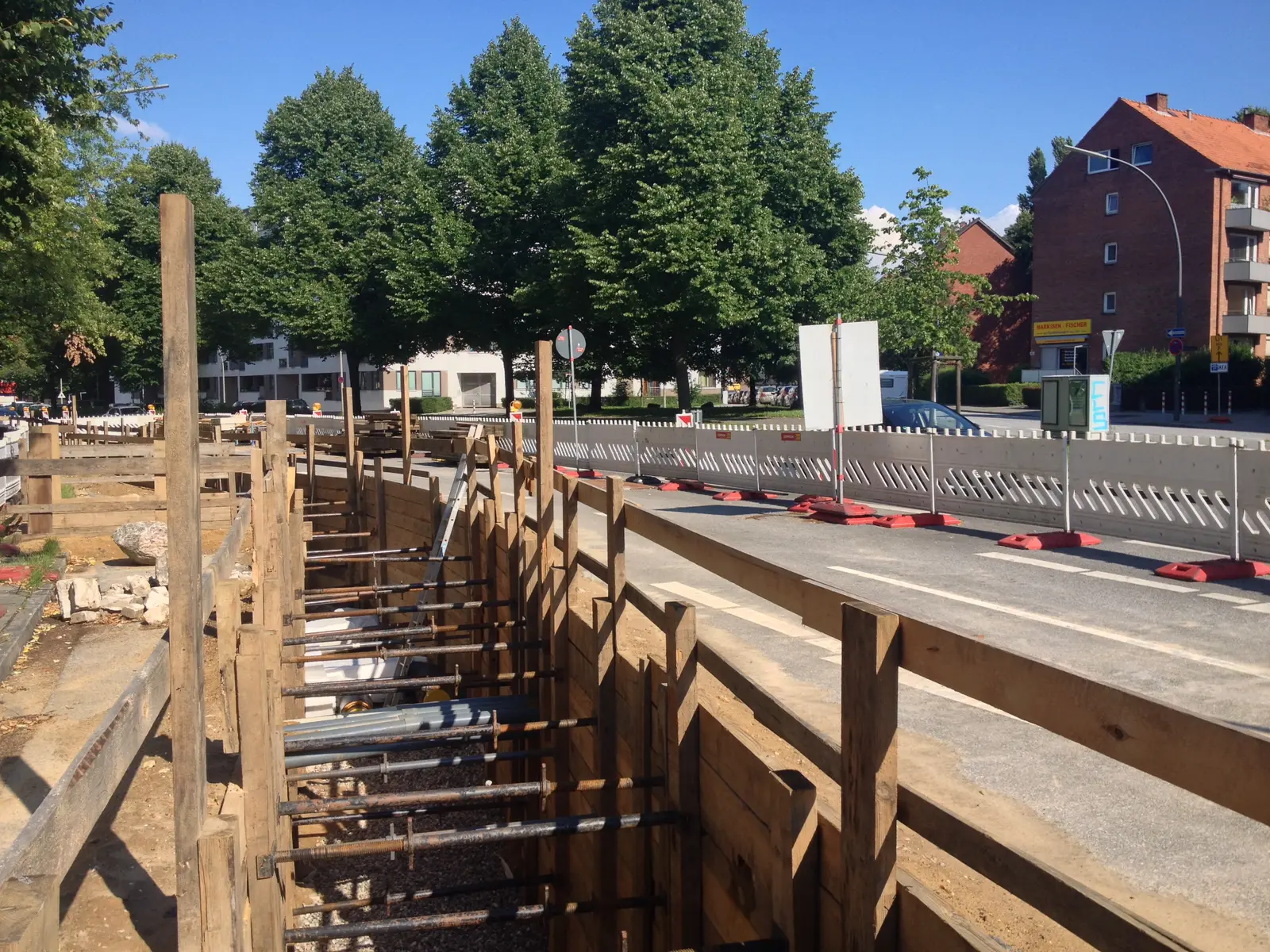
Photo: Cvoelker · CC BY 4.0 · via Wikimedia Commons
Installation Methods
Depending on the terrain, existing infrastructure, and pipe system, different installation methods are used. The three basic variants differ considerably in effort, cost, and area of application.
Above-Ground Installation
In above-ground installation, the pipelines run on pedestals, pendulum supports or pipe bridges. This method is rare in Central Europe and mostly confined to industrial sites or power plant premises, where the visual impact matters little and easy access for maintenance and inspection is welcome.
Three points need attention. The pipe insulation has to be protected against solar radiation, typically by sheet metal cladding or UV-resistant coverings. Exposed pipelines weather over time, so suitable coatings or claddings guard against corrosion. And because above-ground pipelines expand freely, expansion loops or compensators must be planned for the thermal movement.
Underground Installation in Open Trench (Direct Burial)
Direct burial in an open trench is the standard method for thermal networks. It combines a high degree of prefabrication with comparatively low construction effort and works for most route configurations. Civil engineering contractors have extensive experience with it. Factory pre-insulated pipe systems (KMR, flexible pipes) keep the prefabrication high, the buried pipelines are well protected against mechanical damage and weathering, the landscape and urban environment stay undisturbed, and branch chambers keep future extensions accessible.
The typical trench depth is 0.80 to 1.20 m (top of pipe), depending on frost depth, traffic loading and local regulations. Road areas with heavy traffic loading call for greater cover depth.
Trenchless Installation
Where an open trench is not feasible or not economical, such as when crossing roads, railway lines or watercourses, trenchless methods take over.
Horizontal directional drilling (HDD) is a steered method: a pilot bore is created first, then enlarged to the required diameter, after which the pipeline is pulled in. HDD reaches lengths up to about 150 m, allows curved route alignments and is frequently used to cross watercourses and traffic routes.
In pipe jacking, a casing pipe is hydraulically pushed through the ground and the carrier pipeline is later installed inside it. The method suits short distances and diameters up to about DN 200, and it needs a launch pit and a reception pit.
An inverted siphon (Dueker) is a pipeline section that passes beneath an obstacle such as a watercourse. It is often built as a combination of open excavation and trenchless work and demands special measures for tightness and corrosion protection.
Route Planning
Route planning defines the precise alignment of the pipelines in the terrain. It takes into account technical, legal, and economic boundary conditions and has a significant impact on construction costs.
Rigid Pipe Systems
For rigid pre-insulated bonded pipes (KMR) made of steel, changes of direction and thermal expansion need particular attention. Pipe statics require bends, elbows and anchor points to be arranged so that the thermally induced forces are safely absorbed. A longitudinal profile of the route is mandatory to locate high points for venting, low points for drainage and the gradient conditions. Changes of direction are realised either with prefabricated bends or by elastically bending the pipe string within the permissible radii.
Flexible Pipe Systems
Flexible pipe systems (e.g., made of PE-Xa or PB with PUR insulation) considerably simplify route planning. Changes of direction can be achieved without separate fittings through natural bending of the pipe. Installation is carried out from the drum, enabling long runs without joints. Expansion problems are significantly less pronounced than with rigid systems due to the material properties.
Approval Procedures
The installation of district heating pipelines in public ground typically requires approval from the responsible municipality or canton. This procedure can — depending on the complexity of the route and the authorities involved — take up to six months. Early coordination with the approval authorities and utility owners is therefore strongly recommended.
Minimum Clearances to Other Utilities
Numerous pipelines and cables run underground, to which defined minimum clearances must be maintained. Typical values according to applicable standards:
| Utility | Parallel Routing | Crossing |
|---|---|---|
| Gas pipelines | >= 0.40 m | >= 0.20 m |
| Power cables | >= 0.40 m | >= 0.20 m |
| Drinking water pipes | >= 0.40 m | >= 0.20 m |
| Telecommunications | >= 0.30 m | >= 0.20 m |
Utility location information must be obtained before construction starts, and the actual position of existing lines is best verified on site with trial trenches.
Common Installation Situations
The challenges differ with the surroundings. In paved road areas, breaking up and restoring the surface is a considerable cost, and the work has to be coordinated with the road owner and other utility works, with traffic management and barriers planned in advance. On unpaved agricultural land, installation is simpler and cheaper but requires careful reinstatement of the topsoil and, where applicable, compensation to landowners. On sloping terrain, hillside water and ground stability call for drainage, shoring or slope stabilisation. Across private land, a pipeline needs a contractually secured easement registered in the land registry. For later connections, branching points such as tees or chambers should be provided during initial construction, since tapping into an existing pipeline afterwards means a service interruption or a special procedure like hot tapping under pressure.
Civil Works — Construction Workflow
Civil works for thermal networks follow a systematic workflow that can be divided into three main phases.
Trench Excavation
The trench is excavated mechanically. Its width follows from the pipe diameter and the working space required, typically 0.60 to 1.20 m for single pipelines. From a depth of 1.50 m, shoring with struts or trench sheets is mandatory to protect workers. Two trench profiles are common: a sloped trench in open areas with enough space, where the slope gradient depends on the soil type (typically 1:1 to 1:0.5); and a shored trench in confined conditions, particularly in road areas, where trench sheets or planks secure the walls. Wall penetrations at building connections are core-drilled and sealed with suitable sleeves.
Pipe Installation
After excavation, the pipe installation follows. Certified welders join the steel pipes, and the welds are inspected to the applicable standards (such as EN 13941) by visual inspection, ultrasonic testing or radiography, depending on the requirements. The joints of the pre-insulated pipes are then filled on site with PUR foam and sealed with shrink sleeves or couplings; this step is quality-critical, since defective joints are the most common cause of damage in district heating networks. Before backfilling, the whole pipeline undergoes a pressure test, typically at 1.3 times the operating pressure, and only a successful test clears the trench for backfilling. At branches, high points for venting and low points for drainage, chambers are installed so that maintenance and operation can reach the pipeline later.
Trench Backfilling
Backfilling proceeds in several layers and is critical for the long-term protection of the pipelines:
- Pipe bedding: the pipelines are surrounded with fine gravel or sand (grain size <= 0.075 mm), which protects the insulation from sharp-edged stones and spreads the overburden load evenly. The bedding reaches typically 10 to 15 cm above the top of the pipe.
- Backfill: the trench is filled in layers 30 to 50 cm thick with the excavated material or suitable imported material, each layer mechanically compacted to prevent later settlement.
- Base course and surfacing: in road areas, the pavement structure (base course, binder course, surface course) is restored properly, with compaction meeting the traffic loading.
- Surface restoration: green areas, footpaths and other surfaces are returned to their original condition, and on agricultural land the topsoil is reinstated layer by layer.
Planning installation and civil works
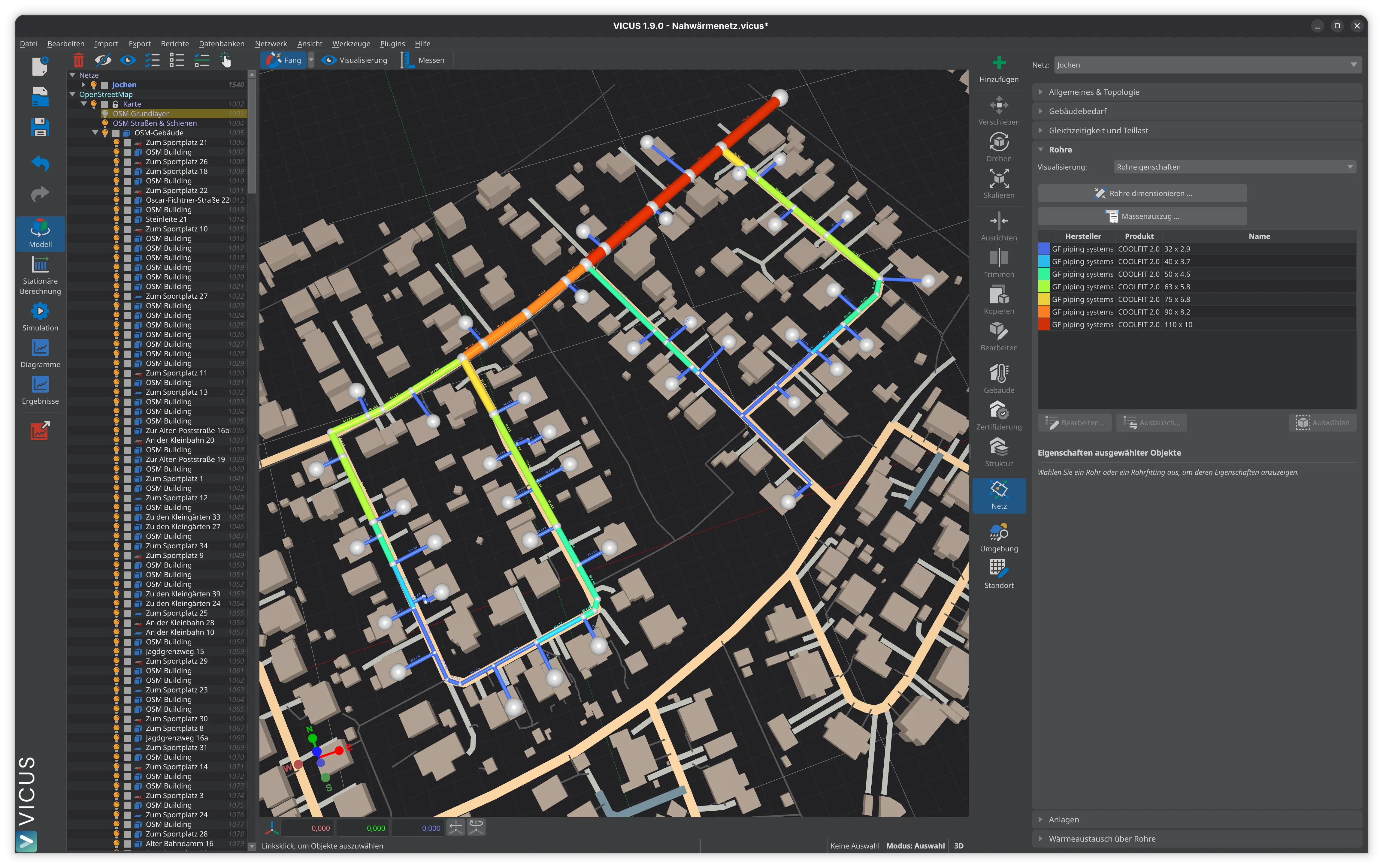
Installation and civil works are the most cost-intensive phases in building a thermal network. Early, careful route planning that accounts for approval procedures, existing utilities and installation methods lays the ground for an economical project. The quality of the work on site, particularly welding, joint assembly and trench backfilling, determines the service life of the network over decades. Planning software such as VICUS Districts supports route planning by computing optimal pipeline alignments and helps to keep costs down as early as the design phase.
Further reading: Pipe Systems Compared compares the available pipe system families and their suitability for different installation methods, Heat Loss Calculation shows how burial depth and insulation affect network losses, and Planning Phases for Thermal Networks describes when in the planning process the installation method is determined.
References and Standards
- AGFW FW 401 — Installation and Statics of Pre-insulated Bonded Pipes in District Heating Networks
- DIN EN 13941 — District Heating Pipes — Design and Installation of Factory-insulated Bonded Pipe Systems
Frequently Asked Questions
How deep are district heating pipes buried?
What trenchless installation methods are available for district heating?
How much does civil works cost for a heating network?
Related Articles
Overview and comparison of pipe systems for thermal networks: KMR, MMR, PMR, PE pipes, ductile cast iron, GRP, and SMR
Thermal network topology: pipe hierarchy, radial, ring, and meshed networks compared. System variants and selection criteria for planning.
Thermal expansion and stress in district heating pipes: calculation formulas, cold installation, pre-stressing and expansion compensation — explained with worked examples.
Disclaimer: The content of this page is for general information purposes only and does not constitute legal, planning or engineering advice. All information is provided without guarantee. Despite careful research, VICUS Software GmbH assumes no liability for the accuracy, completeness or timeliness of the information provided. Third-party product names and trademarks are mentioned for informational purposes only and are the property of their respective owners.