IFC Import for Building Simulation
From BIM model to simulation: how IFC files improve the workflow between CAD and building simulation
Table of Contents
IFC import transfers a BIM model (Industry Foundation Classes, ISO 16739) directly into simulation software, automatically importing building geometry, space objects, component layers and, in well-maintained models, thermal properties. Compared with manual geometry input, IFC import reduces the time required from hours or days to minutes and significantly lowers transfer errors when setting up a dynamic building simulation. This enables close integration between architectural design and energy evaluation already in early planning phases.

What is the IFC format?
Background and standardisation
IFC is an international standard (ISO 16739) developed and maintained by buildingSMART International. The format describes a building as a structured data model with geometric and semantic information. Unlike pure geometry formats such as DXF or STL, IFC contains not only coordinates and surfaces but also information about what an object is: a wall, a slab, a window, a room.
The currently widespread version is IFC4 (ISO 16739-1:2018), although in practice many projects still work with IFC2x3. Both versions are in principle suitable for building simulation, with IFC4 offering expanded possibilities for describing thermal properties.
Structure of an IFC file
An IFC file organises the building hierarchically: project → site → building → storey → spaces and components. Every building component (IfcWall, IfcSlab, IfcWindow, IfcDoor, IfcRoof) has a geometric representation and can be supplied with property sets, which can contain, for example, the U-value, the layer assembly or the g-value of a glazing.
For building simulation, the space objects (IfcSpace) are particularly relevant. They define the thermal zones that serve as the balance volumes in the simulation. Each IfcSpace has a geometric extent and is enclosed by components whose assignment is described via relations (IfcRelSpaceBoundary).
Which data is transferred?
Geometry
The most important contribution of IFC import is the transfer of the three-dimensional building geometry. Walls, slabs, roofs, windows and doors are imported with their exact dimensions, positions and orientations. The simulation software detects which surfaces face outward (exterior components), which border neighbouring zones (interior components) and which border the ground (floor components).
Typical geometric data from the IFC import:
- Wall surfaces with thickness and orientation (azimuth, inclination)
- Window surfaces with position within the wall
- Room volumes and net floor areas
- Storey heights and building outlines
- Position of shading elements (balconies, overhangs)
Component layers and materials
If the BIM model is carefully maintained, it contains information on component layers (IfcMaterialLayerSet) with layer thicknesses and material designations. In favourable cases, thermal properties are also stored: thermal conductivity , density and specific heat capacity . In practice, however, these data are often missing or incomplete, so that the thermal properties must be added manually after import or assigned from material libraries.
Spaces and zones
The IfcSpace objects form the basis for the thermal zones of the simulation. An IfcSpace typically corresponds to a room. For the simulation, several rooms can be grouped into a single zone if they have similar usage conditions and thermal properties. The assignment of rooms to zones is usually carried out after the import in the simulation software.
Challenges with IFC import
Geometric consistency
BIM models are primarily created for architectural design, not for thermal simulation. The requirements on the geometry differ: for the simulation, rooms must form closed volumes, components must not overlap, and windows must lie exactly within the associated wall. In architectural practice, however, small gaps, overlaps or unassigned components often occur.
Typical geometric problems:
- Gaps between components: walls that do not connect exactly to ceilings or other walls create undefined regions.
- Duplicate surfaces: components that partly overlap lead to incorrect area calculations.
- Missing room closures: rooms without a closed envelope cannot be balanced as thermal zones.
- Unassigned windows: windows that do not lie exactly within a wall are not recognised during import.
Missing semantic information
Even when the geometry is correct, the semantic information required for the simulation is often missing. Component layers are not defined, materials have no thermal parameters and rooms are not assigned to a usage category. In many projects, the greatest effort after IFC import is the addition of this information.
Level of detail
Architectural models often contain details that are irrelevant for thermal simulation: railings, rain gutters, installation shafts, furniture. These objects increase the complexity of the simulation model without adding value. Good import tools, as described in the software comparison, automatically filter out such objects or provide the option to import them selectively.
Typical workflow: from CAD model to simulation
A typical BIM-to-simulation workflow comprises the following steps:
-
Model export from CAD: the architectural model is exported from Revit, ArchiCAD or another BIM program as an IFC file. An export profile should be used that contains the information relevant to the simulation (space objects, component layers, space boundaries).
-
Import into the simulation software: the IFC file is imported into the simulation software. The program reads in geometry, components and rooms and creates an initial simulation model.
-
Geometry check and clean-up: the imported model is checked for geometric errors. Gaps, overlaps and missing assignments are corrected. This step usually requires manual rework.
-
Assignment of thermal properties: component layers are supplied with thermal properties, glazings are given g-values and U-values, and rooms are assigned to usage profiles for comfort analysis.
-
Addition of simulation-specific data: climate data, ventilation rates, HVAC systems and control strategies are added, information that is not contained in the architectural model.
-
Simulation and evaluation: the complete model is simulated and the results are evaluated.
IFC vs. manual geometry entry
| Criterion | IFC import | Manual entry |
|---|---|---|
| Time required (geometry) | Minutes to a few hours | Hours to days |
| Geometric accuracy | High (if BIM model is correct) | Depends on the user |
| Error susceptibility | Import problems possible | Input errors possible |
| Rework required | Yes (thermal data, clean-up) | Yes (thermal data) |
| Updatability | Re-import on design change | Manual adjustment |
| BIM model required | Yes | No |
The greatest advantage of IFC import becomes apparent with design changes: when the architecture changes, the updated BIM model can simply be re-imported instead of manually replicating all changes in the simulation software.
DXF as an alternative
In addition to IFC, the DXF format (Drawing Exchange Format) is also frequently used in practice for geometry transfer. DXF describes pure 2D or 3D geometry without any semantic information. It is suitable when no BIM model is available or when only floor plans serve as a basis. However, the effort for post-processing is significantly higher than with IFC import, since all components have to be defined and assigned manually. DXF provides only the geometric basis; all semantic enrichment has to be carried out in the simulation software.
What makes the import work
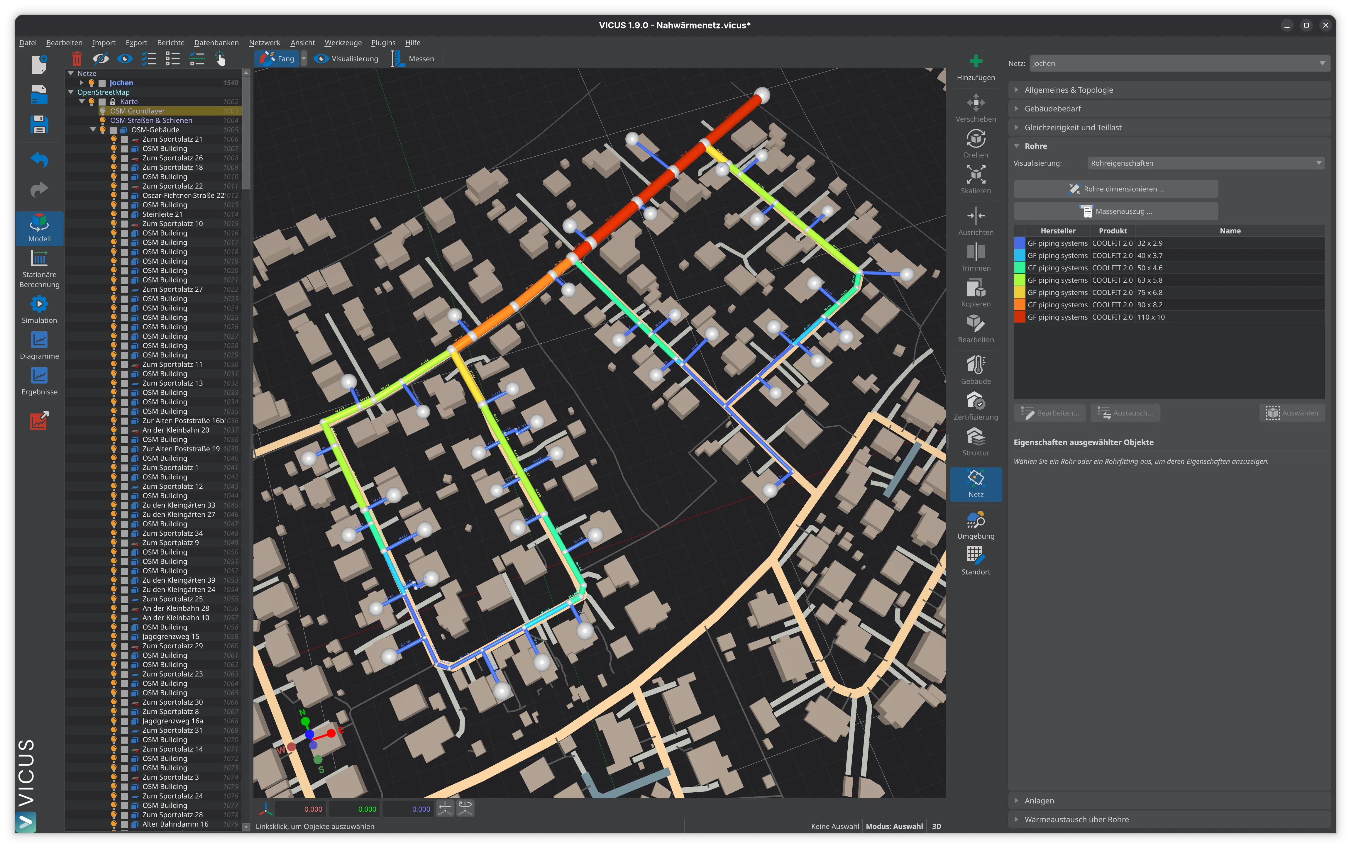
IFC import is the most efficient way to transfer an architectural model into a building simulation. It saves considerable time in geometry input and reduces transfer errors. Its success, however, depends heavily on the quality of the BIM model: cleanly modelled space objects, correct component assignments and complete space boundaries are the prerequisites for a smooth workflow. The thermal enrichment of the model, meaning material assignment, usage profiles and HVAC systems with correct efficiency ratings, remains a task that requires expertise in building simulation even with a good IFC import. VICUS Buildings supports IFC import and thus enables a direct transition from the BIM model to thermal simulation. The BIM-to-simulation workflow will keep improving in the coming years, as both BIM software and simulation tools refine their IFC interfaces.
Further reading: Dynamic Building Simulation — the simulation method that uses imported BIM geometry, Building Simulation Software Comparison — how different tools handle model import and IFC support, Indoor Climate and Comfort Analysis — analysis applications that build on the imported model.
References and Standards
- ISO 16739 — Industry Foundation Classes (IFC) for data sharing in the construction and facility management industries
- buildingSMART International: IFC Specifications (open standard, continuously updated)
- VDI 2552 Part 1 — Building Information Modeling — Fundamentals
Frequently Asked Questions
What is IFC import in building simulation?
What problems commonly occur during IFC import?
Which simulation programs support IFC import?
Related Articles
Building simulation explained: dynamic vs. steady-state calculation, fields of application, result quantities and software for thermal building simulation.
Summer thermal protection by simulation: solar heat gain coefficient vs. dynamic thermal building simulation per DIN 4108-2 – methods, overheating degree hours and limits.
Comparison of steady-state energy demand calculation and dynamic simulation: methods, accuracy and fields of application
EnergyPlus, IDA ICE, TRNSYS and VICUS Buildings: overview and comparison of the leading simulation programs
Disclaimer: The content of this page is for general information purposes only and does not constitute legal, planning or engineering advice. All information is provided without guarantee. Despite careful research, VICUS Software GmbH assumes no liability for the accuracy, completeness or timeliness of the information provided. Third-party product names and trademarks are mentioned for informational purposes only and are the property of their respective owners.