Hydraulic Circuit Types
Basic hydraulic circuits with diagrams: throttle, diverting, mixing and injection circuits for heating, ventilation and district heating compared.
Table of Contents
Basic hydraulic circuits define how a consumer (radiator circuit, underfloor heating, air heater, storage tank or heat exchanger) is connected to a manifold or heat network and how its output is controlled. There are two families. With flow control (throttle circuit, diverting circuit), the flow rate through the consumer changes while the supply temperature stays constant. With mixing control (mixing circuit, injection circuit), the flow rate in the consumer circuit stays constant and the supply temperature is controlled. The choice of circuit determines the return temperatures, the requirements on the manifold and the hydraulic interaction between parallel heating groups.
In the diagrams in this article the manifold is at the bottom and the consumer at the top. Red is supply water at distribution temperature, orange is water at mixed temperature, blue is return water.
Throttle Circuit
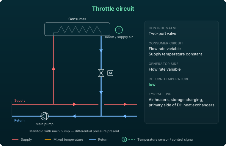
The throttle circuit is the simplest circuit type. A two-port valve throttles the flow rate through the consumer directly. The flow rate varies on both the consumer and the generator side, so partially closing the valve reduces the flow through the whole circuit. The supply temperature at the consumer equals the distribution temperature.
The throttle circuit is subject to differential pressure and needs a variable-speed main pump to hold a stable differential pressure at varying flow rates. For indirect connection to thermal networks, it is the preferred circuit on the primary side of the heat exchanger.
Advantages:
- Low return temperatures, especially at part load
- Straightforward individual room control via thermostatic valves
- Low equipment complexity, no separate circuit pump
Drawbacks:
- Freezing risk with air heaters when the flow rate drops sharply at part load
- Uneven temperature distribution across large heating surfaces at low flow
Typical applications: storage charging, air heaters without frost risk, zone control in larger buildings, indirect district heating connections with heat exchangers.
Diverting Circuit
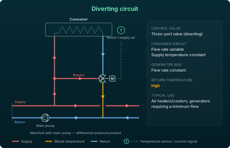
In the diverting circuit, a three-port valve sits in the consumer return. A bypass connects the supply to the valve’s third port. The valve splits the flow between consumer and bypass: the lower the required output, the more supply water flows past the consumer straight into the return.
The flow rate at the manifold therefore stays constant while the flow rate through the consumer varies. The downside is the return: at part load, hot bypass water mixes into the return and the return temperature rises. This makes the diverting circuit unsuitable for district heating, condensing boilers and heat pumps.
Advantages:
- Constant flow rate on the generator side, no feedback from consumer control on the main pump
- Supply temperature at the consumer stays constant
Drawbacks:
- High return temperatures at part load
- Freezing risk with air heaters, as with the throttle circuit
Typical applications: air heaters and coolers, generators with a required minimum flow, systems that need a constant flow rate in the distribution network.
Mixing Circuit
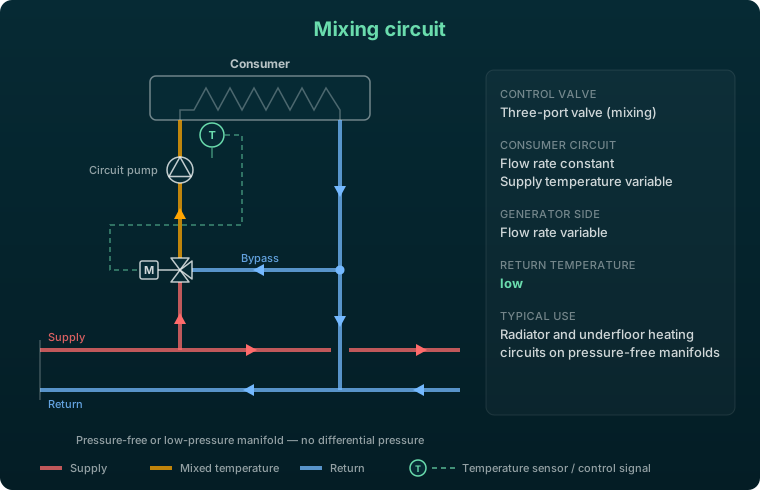
In the mixing circuit, return water from the consumer circuit is blended with the hot supply water to reach the desired supply temperature in the consumer circuit. A three-port valve in the supply does the blending, continuously adjusting the ratio of manifold supply to bypass water. The flow rate in the consumer circuit stays roughly constant, while the flow rate on the manifold side varies.
A mixing circuit needs a pressure-free or low-pressure manifold, typically with a hydraulic separator, without significant differential pressure of its own. The circuit pump alone provides the circulation in the consumer circuit.
Advantages:
- Low return temperatures, since only cooled water flows back to the manifold
- Good control of the supply temperature
- Even temperature distribution across the heating surface
- No differential pressure needed at the manifold
Drawbacks:
- Requires a pressure-free or low-pressure manifold; on a pressurized manifold the main pump pushes water through the bypass and control becomes unstable
- Sluggish response when the pipes between manifold and mixing valve are long
Typical applications: radiator circuits, underfloor heating and systems with condensing heat generators, where low return temperatures pay off particularly well.
Mixing circuit with fixed pre-mixing (double mixing)
If the distribution temperature is much higher than the required supply temperature, the mixing valve works almost permanently at small openings and controls poorly. A fixed bypass with a balancing valve is then added, blending in return water before the valve. As a rule of thumb, fixed pre-mixing is needed when
A typical case is underfloor heating at 35 °C supply on a boiler or district heating manifold at 70 °C or more.
Injection Circuit with Three-Port Valve
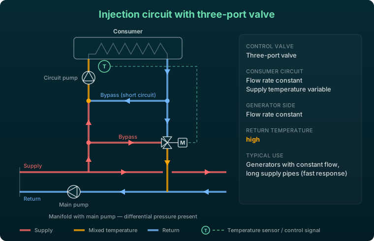
In the injection circuit, the main pump pushes hot supply water into the consumer circuit. A bypass between supply and return of the consumer circuit decouples the main pump from the circuit pump and blends in return water. In the three-port valve variant, the valve sits in the return and a second bypass connects it to the supply.
Both flow rates are therefore constant: the circuit pump keeps the consumer flow constant, and on the manifold side the three-port valve diverts unused supply water straight into the return. Because hot water circulates right up to the consumer circuit, the circuit responds quickly even with long supply pipes. As with the diverting circuit, however, the return temperature rises at part load.
Advantages:
- Short response time even over long distances between manifold and consumer
- Constant flow rate on both generator and consumer side
- Even temperature distribution across the heating surface, no freezing risk for air heaters
Drawbacks:
- High return temperatures at part load, unsuitable for district heating and condensing technology
- Two pumps and differential pressure at the manifold required
Typical applications: generators that require a constant flow rate, extensive distribution networks with long supply pipes, air heaters at risk of freezing.
Injection Circuit with Two-Port Valve
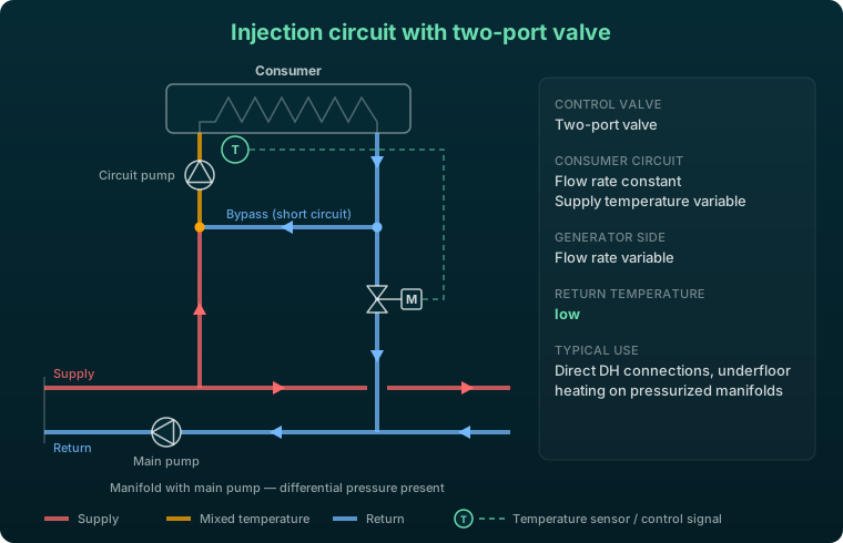
The two-port valve variant has no bypass on the manifold side. The valve in the return determines how much supply water is injected into the consumer circuit; the bypass in the consumer circuit supplies the remainder of the constant consumer flow as return water.
The flow rate in the consumer circuit stays constant while the flow rate on the manifold side varies with the valve position. Since only cooled water returns to the manifold, return temperatures are low. The variable flow on the manifold side requires a variable-speed main pump to keep the differential pressure stable.
Advantages:
- Low return temperatures through full cooling
- Good controllability even on pressurized manifolds and networks
- Multiple parallel heating circuits barely influence one another hydraulically
Drawbacks:
- Two circulation pumps required (main pump and circuit pump)
- Differential pressure must be present at the manifold
Typical applications: district heating connections (direct and indirect), domestic hot water preparation, underfloor heating and radiator circuits on pressurized manifolds, systems with multiple parallel heating groups.
Injection Circuit vs. Mixing Circuit
Both circuits control the supply temperature at a constant flow rate in the consumer circuit. The difference is the manifold:
- Pressure-free manifold (hydraulic separator, buffer tank): mixing circuit. The circuit pump draws through the mixing valve; there is no main pump pushing into the heating circuit.
- Manifold with differential pressure (main pump, district heating network): injection circuit. The bypass prevents the main pump and the circuit pump from working against each other.
Within the injection circuit, the return temperature decides: the two-port valve gives low return temperatures and is the right choice for district heating, condensing boilers and heat pumps. The three-port valve only makes sense when the generator needs a constant flow rate or long supply pipes require a fast response.
Comparison of Circuit Types
| Circuit | Control valve | Consumer flow rate | Generator-side flow rate | Return temperature | Manifold |
|---|---|---|---|---|---|
| Throttle circuit | Two-port valve | variable | variable | low | with differential pressure |
| Diverting circuit | Three-port valve | variable | constant | high | with differential pressure |
| Mixing circuit | Three-port valve | constant | variable | low | pressure-free / low-pressure |
| Injection circuit, three-port valve | Three-port valve | constant | constant | high | with differential pressure |
| Injection circuit, two-port valve | Two-port valve | constant | variable | low | with differential pressure |
Control Valve and Valve Authority
Every hydraulic circuit type depends on the control valve being sized correctly. The key parameter is the value, which gives the volume flow rate in that passes through the fully open valve at a pressure drop of 1 bar (100 kPa):
where is the nominal volume flow rate, is the reference pressure loss and is the actual pressure drop across the valve.
The valve authority describes the ratio of the pressure drop across the fully open valve to the total pressure drop of the controlled circuit:
Adequate valve authority is what gives a stable, proportional control characteristic. If it is too low, the characteristic becomes distorted and the valve modulates only in the last portion of its stroke, which leads to unstable behaviour. The following minimum values apply:
- Three-port valves:
- Two-port valves: , i.e. at least 30% of the maximum differential pressure drops across the valve
As a guideline for the minimum pressure drops across the control valve:
| Circuit type | Minimum pressure drop across valve |
|---|---|
| Pressure-free manifold (mixing) | 3 kPa |
| Low-pressure manifold, 1 group | 5 — 20 kPa |
| Injection/throttle circuit | 10 — 20 kPa |
Direct and Indirect Connection
The choice of hydraulic circuit type also depends on whether the thermal network is connected directly or indirectly.
With a direct connection, the network water flows straight through the building-side installation. No heat exchanger is needed, which simplifies the design and reduces investment costs. The trade-off is that the building installation must withstand the pressurization level of the network, and the network water quality acts directly on the building components. Injection circuits with two-port valves and throttle circuits are especially common here.
An indirect connection separates the hydraulics with a heat exchanger, usually a plate type. Primary and secondary circuits are decoupled in pressure, so the secondary side can run at a separate, lower pressure level. On the primary side of the heat exchanger, the throttle circuit is the preferred option, since it combines the simplest design with low return temperatures.
Hydraulic circuits in VICUS Districts:
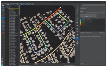
Hydraulic circuits are not selected as ready-made types but assembled freely from pipes, pumps, valves and heat exchangers in the plant editor. The solver calculates mixing temperatures at network nodes automatically from the mass and energy balance.
Matching circuit to application
- Low return temperature required (district heating, condensing boiler, heat pump): throttle circuit, mixing circuit or injection circuit with two-port valve.
- Pressure-free manifold with hydraulic separator: mixing circuit, with fixed pre-mixing for large temperature differences.
- Manifold or network with differential pressure, constant flow in the heating circuit: injection circuit with two-port valve.
- Generator with minimum flow or very long supply pipes: diverting circuit or injection circuit with three-port valve, accepting higher return temperatures.
- Air heaters at risk of freezing: a circuit with constant flow in the consumer circuit (mixing or injection circuit).
In every case, sizing the control valve correctly, above all keeping the minimum valve authority, is what makes operation stable and energy-efficient. In VICUS Districts, the circuit types can be modelled directly in the network model and their hydraulic interaction simulated dynamically.
Further reading: Transfer Stations describes the complete design of the heat transfer station in which the circuit types are embedded, Hydraulic Balancing covers the coordination of hydraulic resistances for uniform supply to all consumers, and Network Temperatures explains the temperature conditions that must be considered when selecting the circuit type.
References and Standards
- VDI 2073 Part 1 — Hydraulics of water-based systems — Fundamentals
- Recknagel, H.; Sprenger, E.; Schramek, E.-R.: Taschenbuch fuer Heizung + Klimatechnik. DIV Deutscher Industrieverlag (standard reference, continuously updated).
- Siemens Building Technologies: Hydraulics in building systems (fundamentals documentation).
- DIN EN 12828 — Heating systems in buildings — Design of water-based heating systems
Frequently Asked Questions
Which basic hydraulic circuits are there?
What is the difference between an injection circuit and a mixing circuit?
What is valve authority and what minimum values apply?
When is a direct vs. indirect network connection used?
Related Articles
How to size house transfer stations: domestic hot water priority, space heating loads and diversity factors — with sizing guidance for district heating connections.
Central vs. decentralised pump concepts: sizing, index-point control and energy demand
What is a heating curve and how does it affect the design of district heating networks and heat pumps?
Pump switching and control in district heating networks: parallel and series configurations, redundancy concepts and differential-pressure control.
Disclaimer: The content of this page is for general information purposes only and does not constitute legal, planning or engineering advice. All information is provided without guarantee. Despite careful research, VICUS Software GmbH assumes no liability for the accuracy, completeness or timeliness of the information provided. Third-party product names and trademarks are mentioned for informational purposes only and are the property of their respective owners.