Meeting Operating Pressure Limits in Heat Networks
What operating pressure, rest pressure, MOP, MIP and the nominal pressure rating mean, why gauge pressure is the working convention, and how the minimum pressure follows from the saturation pressure plus 1.5 bar
Table of Contents
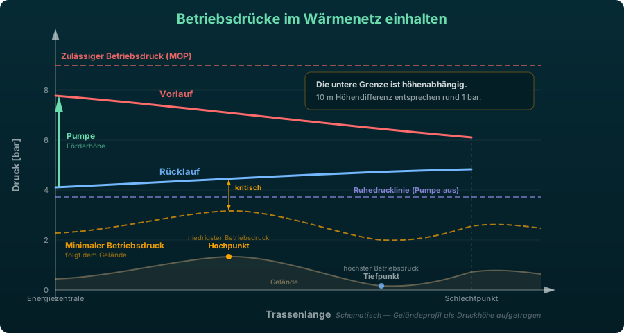
Meeting the operating pressures of a heat network means keeping the pressure everywhere between two limits: below the permissible operating pressure of the weakest component on the path, and above the saturation pressure at the hottest point of the supply line plus a safety margin of roughly 1.5 bar. Both limits depend on elevation, and each becomes governing in a different load case. This article clarifies the terms and supplies the numbers; how the limits appear in the pressure diagram, and what differential pressure has to be available at the index point, is covered by Pressure Profile and Pressure Diagram.
The Pressure Terms
Four terms are regularly confused although they denote different things:
| Term | Meaning |
|---|---|
| Operating pressure | The pressure that actually stands in the pipe during operation — including the geodetic component from the elevation. |
| Rest pressure | The pressure level with circulation at a standstill, imposed by the pressurization system alone. Without pump head the supply line drops to this level. |
| MOP (Maximum Operating Pressure) | The pressure permitted continuously in normal operation for the weakest component on the path. |
| Nominal pressure rating PN | The standardized pressure rating of a component, e.g. PN 16. It is a material property, the MOP an operating figure — the two can diverge. |
Gauge Pressure Is the Working Convention
All of these figures are gauge pressures against the atmosphere: PN, MOP, MIP and the values in a set of technical connection requirements just as much as what a manometer on the network reads. As long as one stays on that scale, calculation and limit compare directly and nothing has to be converted.
Absolute pressure is needed in exactly one place: for the lower limit. The saturation pressure of water is an absolute pressure, because evaporation is a question of the actual pressure in the medium and not of the pressure above the surroundings. For that one comparison the two scales have to be converted into each other:
where:
- : absolute pressure [bar]
- : gauge pressure against the atmosphere [bar]
- : ambient pressure, around 1.013 bar at sea level and only 0.899 bar at 1000 m [bar]
PN 16 therefore corresponds to roughly 17 bar absolute. Checking absolute pressures from a calculation against a nominal pressure rating without conversion stays about 1 bar on the safe side — acceptable, but it should be a deliberate choice rather than an unnoticed one. The opposite mistake is dangerous: holding a gauge pressure directly against the saturation pressure pretends roughly 1 bar of reserve that is not there.
Upper Limit: MOP, MIP and Nominal Pressure Rating
The upper limit is not set by the nominal pressure rating of the pipes but by the lowest permissible pressure rating among all components on the path under consideration. Valves, fittings, expansion compensators, strainers, heat meters, transfer stations, and heat exchangers carry ratings of their own that are frequently below that of the installed pipe system. Pipelines themselves do not fall under the Pressure Equipment Directive, but many of the components listed do. A check that looks only at the pipes can therefore pass formally and still be wrong in practice.
Which pressure ratings the common systems permit — from PN 6 for plastic service pipes to PN 64 for steel jacket pipes — is covered by the comparison of pipe systems.
MIP: The Incident Case
Alongside the MOP stands the MIP (Maximum Incidental Pressure) — the pressure permitted briefly in an incident, for instance when the control system fails, when a valve closes rapidly, or during the pressure surge following a pump failure. Pressure surges arise from the inertia of the water column and can reach a multiple of the steady-state pressure loss; their magnitude depends on the closing time of the valve, the pipe length, and the speed of sound in the medium. They cannot be derived from a steady-state network calculation and require a separate, transient analysis.
Test Pressure
The test pressure of the leak tightness test is set according to the pipe system, the applicable code, and the technical connection requirements (TAB) of the network operator, and is typically 1.3 to 1.5 times the permissible operating pressure. Presenting a single factor as the correct one would be misleading — steel jacket, plastic jacket, and plastic service pipe systems are tested differently, and the operator may impose stricter requirements. The test pressure matters for the pressure design insofar as every installed component has to withstand it.
Lower Limit: Evaporation and Cavitation
If the absolute pressure anywhere in the supply line falls below the saturation pressure at the local temperature, the network water evaporates. The consequences range from cavitation damage on pump impellers and valves through noise generation to a complete break of the water column at high points. The minimum pressure therefore follows from the saturation pressure plus a safety margin:
where:
- : required lowest absolute pressure in the network [bar]
- : saturation pressure at the highest supply temperature occurring [bar]
- bar: margin against evaporation and cavitation
- bar: margin for the control tolerance of the pressurization system and for transients
Status of the Two Margins
The two terms carry different weight and have to be named separately — treating the 1.5 bar as a standard is a faulty argument:
- 0.5 bar against evaporation and cavitation — broad professional consensus, applied consistently in the technical literature and in the planning guides.
- around 1.0 bar for control tolerance and transients — a planning recommendation from Swiss QM district heating practice, not a standard. It covers the fact that a pressurization system holds its setpoint only within a band, and that start-up, changeover, and settling processes briefly depress the pressure.
- In building heating systems (DIN EN 12828, DIN 4807), by contrast, only 0.2 bar is added at high points. That explains the apparently contradictory spread in the literature: smaller, manageable systems with short pipe runs and low stored mass need less reserve than an extended network.
Together the two terms give a safety margin of 1.5 bar above the saturation pressure.
Saturation Pressure of Water
The third column is the resulting minimum absolute pressure at a margin of 1.5 bar:
| Supply temperature [°C] | [bar abs] | Minimum pressure at a 1.5 bar margin [bar abs] |
|---|---|---|
| 70 | 0.31 | 1.81 |
| 80 | 0.47 | 1.97 |
| 90 | 0.70 | 2.20 |
| 100 | 1.01 | 2.51 |
| 110 | 1.43 | 2.93 |
| 120 | 1.99 | 3.49 |
| 130 | 2.70 | 4.20 |
| 140 | 3.61 | 5.11 |
| 150 | 4.76 | 6.26 |
The rise is non-linear: from 70 to 100 °C the saturation pressure grows by 0.7 bar, from 120 to 150 °C by 2.8 bar. Networks with a high supply temperature thereby lose a considerable share of the pressure window between the lower and the upper limit — a hydraulic argument for reduced network temperatures, quite apart from the heat losses.
Intermediate Values from the Antoine Equation
For temperatures between the tabulated values, the saturation pressure can be determined with the Antoine equation — a general engineering formula for describing vapor pressure curves:
where:
- : temperature [°C]
- , , for the range 1 to 100 °C
- , , for the range 100 to 374 °C
The change of parameter set at 100 °C matters: extrapolating the constants of the lower range beyond 100 °C underestimates the saturation pressure and with it the required minimum pressure.
NPSH Condition of the Pump
The lower limit applies not only to high points in the network but also to the suction side of every pump. What governs there is the NPSH condition, covered in detail by the article on pump sizing: if the reserve between the available and the required NPSH value falls below the usual minimum, the pump cavitates even when the network pressure is sufficient everywhere else. How much inlet pressure is available is decided by the way the pressurization system is connected.
The Geodetic Component
Elevation differences produce a static pressure component superimposed on the operating pressure. As a rule of thumb: 10 m of elevation difference correspond to roughly 1 bar, so 1 m to roughly 0.1 bar. The reference point is always the point of pressurization, not the lowest point of the network — the pressurization system imposes a level at the location where it is connected, and all other points lie above or below it by their elevation difference to that location.
A Common Misconception
The geodetic components cancel out — but only in the pump head, not in the pressure levels. Because supply and return travel the same route over the same elevations, the climb in the supply line is compensated by the descent in the return line; the pump therefore only has to cover the friction loss of the closed circuit, no matter how hilly the route is.
For meeting the operating pressures the opposite holds. The highest pressure occurs at the low point and is checked there against the MOP, the lowest at the high point against the evaporation limit — both limits depend directly on elevation, and geodesy shifts them in the same direction. A network can have an unremarkable pump head and still fail on geodesy. How reliable the underlying elevation values are is covered by the article on terrain elevation in network planning.
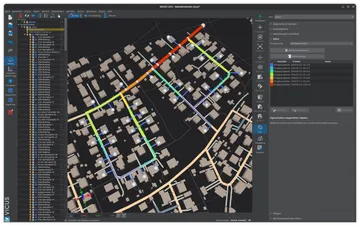
Pressure limits in VICUS Districts:
All computed network pressures are gauge pressures and therefore compare directly with PN and with the values of a technical connection specification. Two quantities are checked: the highest operating pressure against the lowest nominal pressure rating of the pipes on the path, the lowest against the vapour pressure plus the Minimum pressure margin — 1.5 bar by default. Because the vapour pressure is absolute, the ambient pressure is taken out there; it follows from the project altitude. The verdict is written out in the network report and in the status line of the path profile — and the check is performed in the steady state only.
Further reading: Pressure Profile and Pressure Diagram — makes the limits visible in the pressure diagram and covers the differential pressure at the index point, Pressurization and Expansion — sizing the rest pressure and the expansion volume, Pipe Systems Compared — which nominal pressure ratings the systems permit, Terrain Elevation and Topography in Network Planning — origin and accuracy of the elevation values.
References and Standards
- Planungshandbuch Fernwärme. Version 1.3, QM Fernwärme / Verenum — section 3.7 on the pressure profile in the district heating network, p. 58; published in English as Handbook on Planning of District Heating Networks, Version 1.0a
- AGFW FW 442 — Pressurization in Hot Water District Heating Networks
- DIN 4747 — District Heating Systems — Safety Requirements for Hot Water Building Installations
- DIN EN 13941 — District Heating Pipes — Design and Installation of Pre-insulated Bonded Pipe Systems
Frequently Asked Questions
What is the minimum pressure required at the highest point of a heat network?
Does one work with gauge pressure or absolute pressure in a heat network?
What is the difference between MOP and MIP?
Related Articles
Network operating modes in district heating networks: sliding, constant, and sliding-constant operation. Operating principles, advantages and disadvantages compared.
Pressurization systems in thermal networks: open and closed systems, pre-charge pressure from the static height, expansion volume and make-up water
The pressure diagram of a heat network: static pressure, rest pressure and pressure loss, the index point and the minimum differential pressure of 0.5 to 1.0 bar required there
Control concepts for thermal networks: differential pressure control, index point and control with multiple feed-in points
Disclaimer: The content of this page is for general information purposes only and does not constitute legal, planning or engineering advice. All information is provided without guarantee. Despite careful research, VICUS Software GmbH assumes no liability for the accuracy, completeness or timeliness of the information provided. Third-party product names and trademarks are mentioned for informational purposes only and are the property of their respective owners.