Network Control
Control concepts for thermal networks: differential pressure control, critical point and control with multiple feed-in points
Table of Contents
Network control maintains the differential pressure between supply and return at every transfer station within a range of typically 0.4 to 1.0 bar. It does so by adjusting the network pump speed based on differential pressure measurement at the critical point, the location with the lowest available differential pressure. Proportional pressure control, where the differential pressure decreases with falling flow rate, is the standard approach for most thermal networks and is more energy-efficient than constant pressure control at part load. The chosen control strategy directly affects pump energy consumption, supply security, and overall system stability.

Basic Control Concept
Network operation is typically run according to the chosen network operating mode, weather-compensated and time-schedule controlled. The implementation of the pre-control can be achieved through the following systems:
- Supervisory BACS system (Building Automation and Control System)
- PLC of the firing system
- Control system of the energy center
The control concept must handle the following situations:
- Changes in hydraulic network resistance due to consumers switching on and off (influenced by the hydraulic circuit types)
- Minimization of pressure fluctuations in the network through complete compensation of the required differential pressures
- Prevention of pump deactivation at low load (minimum speed approximately 25% of maximum speed)
The Network Critical Point
At one point in the network, the lowest differential pressure between supply and return exists. This point is referred to as the network critical point. Depending on the current heat demand, the critical point can shift.
Supply shortages are most likely to occur in the area of the critical point, which is why the minimum required differential pressure must be maintained here. The differential pressure is generated by the network pumps (see pump sizing).
Location of Differential Pressure Measurement
For optimal control, it is crucial where the differential pressure is measured:
Measurement at the Pump
The simplest variant measures the differential pressure directly at the pump. Disadvantage: Pressure fluctuations in the network are not fully compensated, as changes in network resistance are only detected indirectly.
Measurement in the Network (recommended)
The differential pressure measurement should be taken at one or more reference measurement points in the network, as close to the critical point as possible. This enables:
- Direct measurement of the actual differential pressure at critical locations
- More accurate control, as changes in network resistance are detected immediately
- Optimal pump operating point
As an alternative, the valve position of all transfer stations can also be used as a control variable: actuator feedback signals are used to determine whether the differential pressure is adequate.
Types of Differential Pressure Control
Constant Pressure Control
The differential pressure across the pump is kept constant at varying volume flow rates. The operating point follows a horizontal line in the p-V diagram.
- Simple to implement
- Less efficient at part load
- Suitable for smaller networks with little load variation
Proportional Pressure Control
The differential pressure decreases proportionally with decreasing volume flow rate. The operating point follows a declining line in the p-V diagram.
- More efficient than constant pressure at part load
- No difference from constant pressure when using pressure-independent control valves
- Standard for most thermal networks
Control with Multiple Feed-in Points
When a thermal network has multiple energy centers at different locations, the control of pump groups must be coordinated:
Base Load and Peak Load Center
A typical control concept for two centers:
- Base load operation: only one pump group in operation, control via differential pressure measurement in the network
- Redundancy operation: switchover to the respective other center
- Peak load operation: both pump groups in operation, where one feed-in point acts as master for pressure control and the other operates as slave following a specified heat load or characteristic curve setpoint
Prevention of Flow Stagnation
The algorithm for feed-in from multiple points must ensure that no flow stagnation occurs between the feed-in points. At locations where the zones of influence of two feed-in points meet, the flow direction can reverse. This must be accounted for by the control system and verified through thermo-hydraulic simulation.
Thermal Networks with Highly Variable Flow
In large thermal networks with multiple pumps, the flow rate is often highly variable, while the supply temperature changes comparatively little. For energy-efficient summer operation (< 20% of winter volume flow rate), the use of a separate summer pump has proven effective:
- The control complexity is lower (no sequencing, manual switchover)
- The summer pump can be optimally sized for the reduced load range
- The winter main distribution pump must be able to supply the heat interconnection at 100% at the design point
Hydraulic Balancing as a Prerequisite
Effective network control requires that the network is hydraulically balanced. Without hydraulic balancing, over-supply and under-supply of individual customers occurs, regardless of the quality of the pump control. Modern systems with automatic differential pressure controllers or combination valves at the transfer stations significantly simplify balancing.
Bringing the control elements together
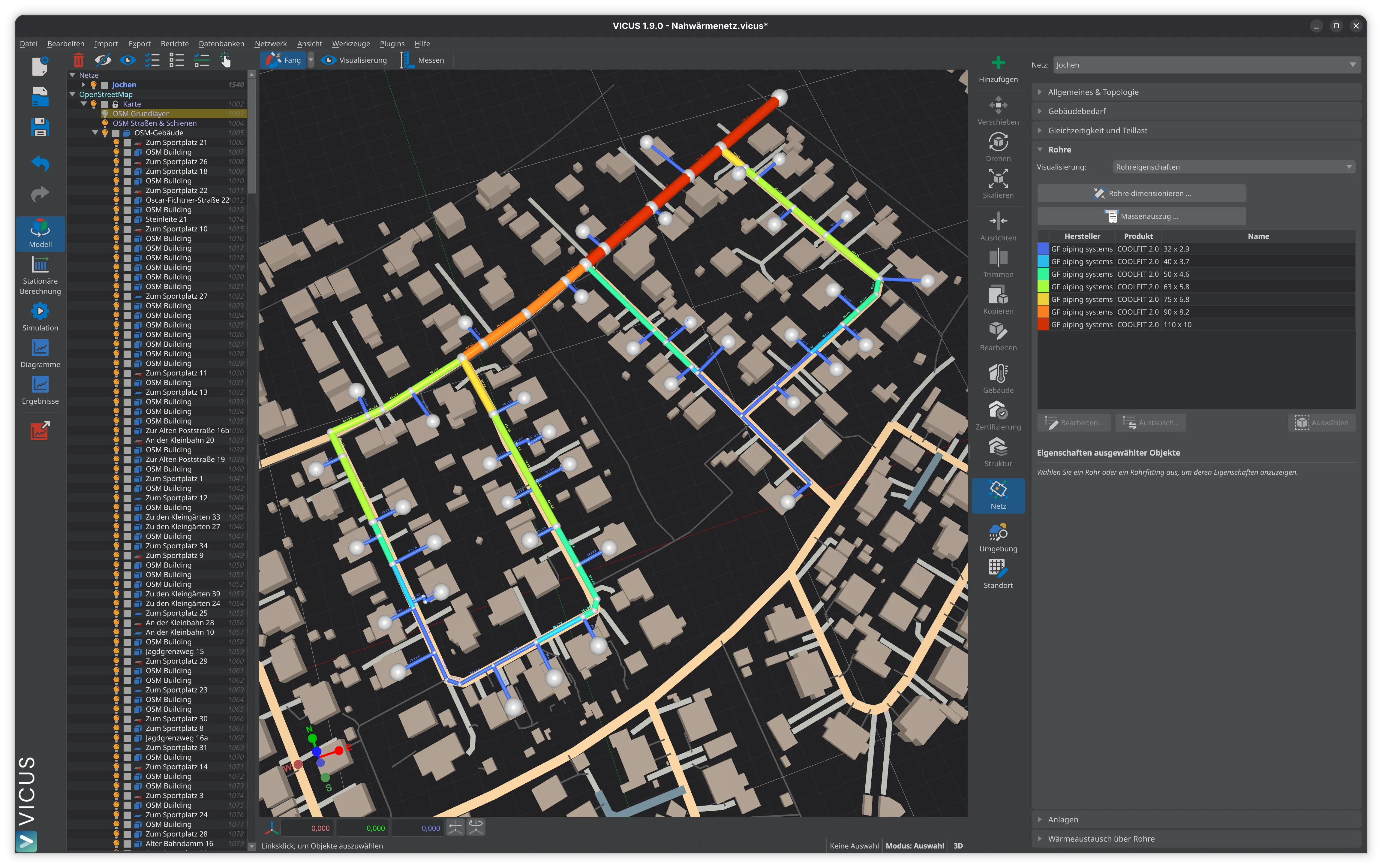
Network control is an interplay of pump control, differential pressure measurement, and hydraulic balancing. Network-based differential pressure control with measurement at the critical point is the established approach and ensures efficient and reliable heat supply. For networks with multiple feed-in points, the coordination of pump groups requires special attention. The effects of different control strategies on network operation can be investigated and optimized with simulation software such as VICUS Districts.
Further reading: Network Operating Modes — the control system implements the chosen operating mode during operation, Pump Switching and Control — pump control is a central component of network control, Digital Twin and Monitoring — digital monitoring and optimization of the control strategy during operation.
References and Standards
- AGFW FW 515 — Control and Regulation in District Heating Networks
- AGFW FW 440 — Hydraulic Calculation of Hot Water District Heating Networks
- VDI 2073 Part 1 — Hydraulics of Water-Based Systems — Fundamentals
Frequently Asked Questions
How does differential pressure control work in a district heating network?
What is the difference between constant pressure and proportional pressure control?
How are district heating networks with multiple feed-in points controlled?
Related Articles
Network operating modes in district heating networks: sliding, constant, and sliding-constant operation. Operating principles, advantages and disadvantages compared.
Pressurization systems in thermal networks: open and closed systems, expansion volume and make-up water
Pressure diagram, operating pressures and pressure conditions in thermal networks: MOP, critical point and total pressure
Disclaimer: The content of this page is for general information purposes only and does not constitute legal, planning or engineering advice. All information is provided without guarantee. Despite careful research, VICUS Software GmbH assumes no liability for the accuracy, completeness or timeliness of the information provided. Third-party product names and trademarks are mentioned for informational purposes only and are the property of their respective owners.