Sizing with multiple energy plants
District heating network, part 8: pipe sizing for networks with multiple energy plants
Overview ▶ 0:09
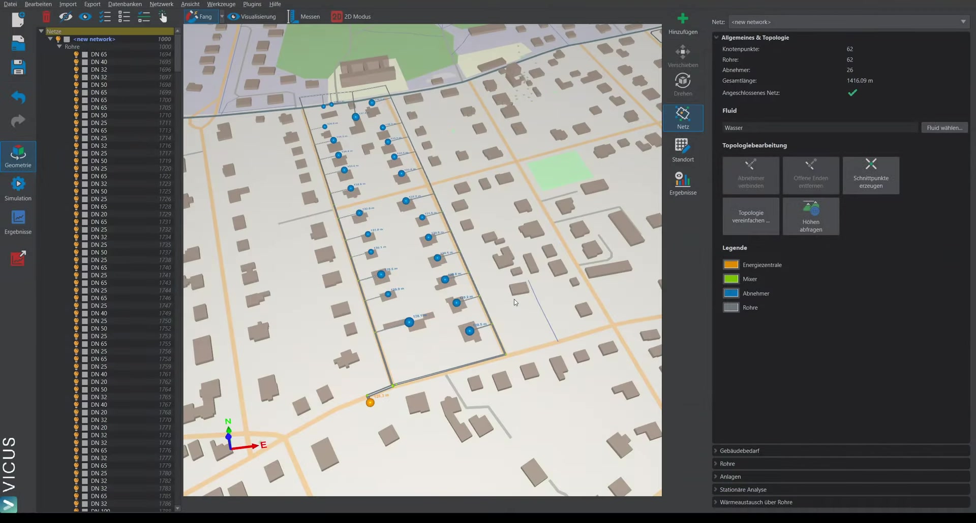
This tutorial demonstrates how to place a second energy plant and perform pipe sizing for a network with multiple feed-in points.
Placing a second energy plant ▶ 0:24
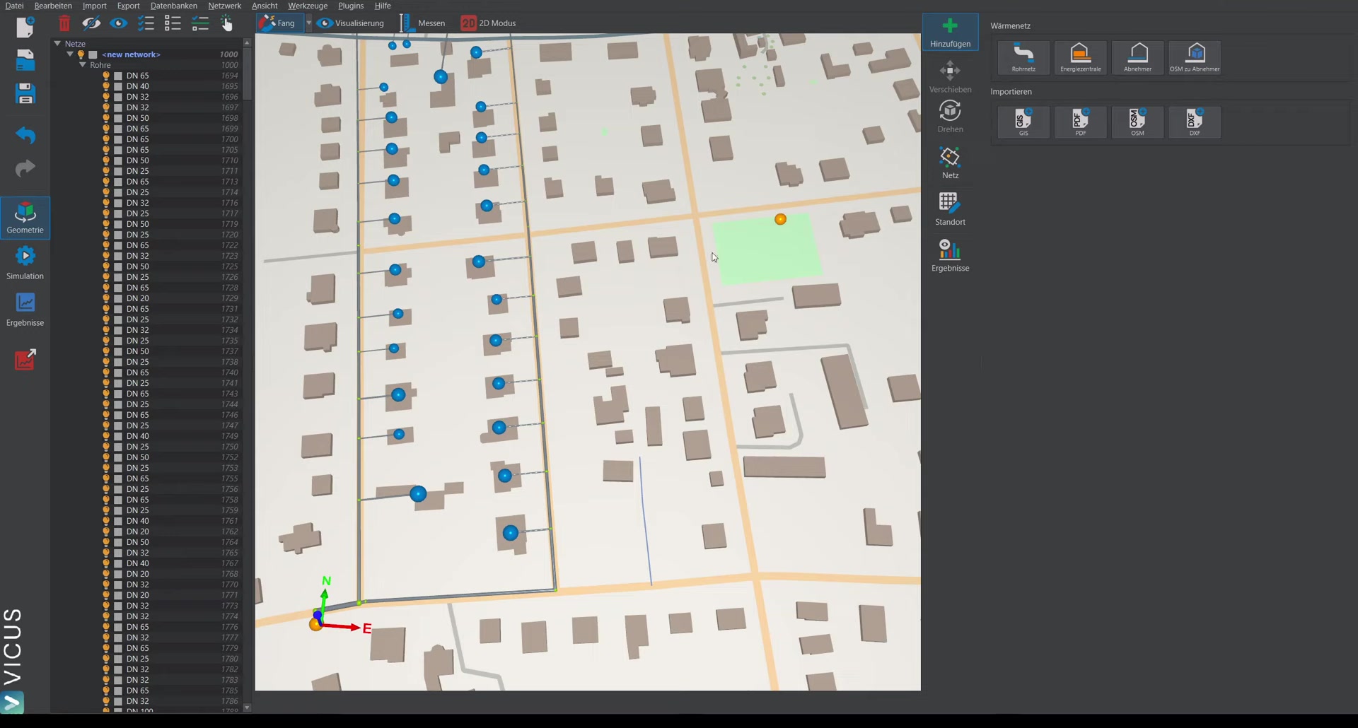
- Switch to the Add tab and select Energy plant.
- Place the energy plant at the desired position and assign a name (e.g. “Heat generator 2”).
- Create the energy plant.
Connecting to the network ▶ 0:42
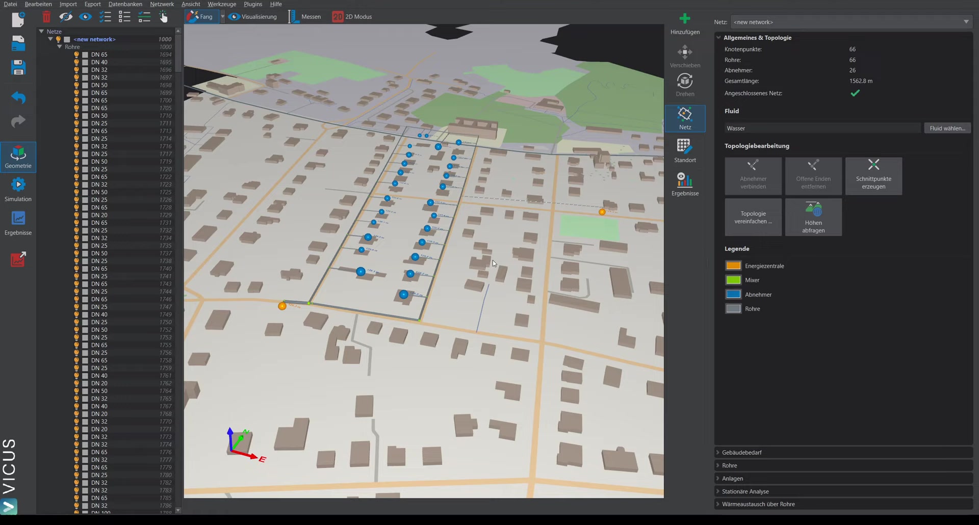
- Draw a new pipe and connect it to the existing network.
- Switch to network mode and Query elevations — this automatically sets the correct elevation.
Pipe sizing with multiple energy plants ▶ 1:15
In pipe mode, open Pipe sizing. As soon as more than one energy plant is present, a new tab appears with the properties of the energy plants.
Settings ▶ 1:33
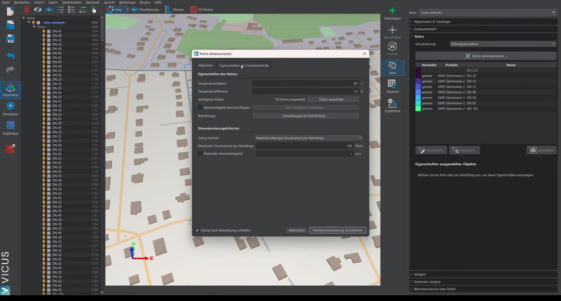
The remaining sizing settings stay the same (e.g. 15 Kelvin temperature spread). The pipes are already selected from the database.
Options for the split ▶ 1:58
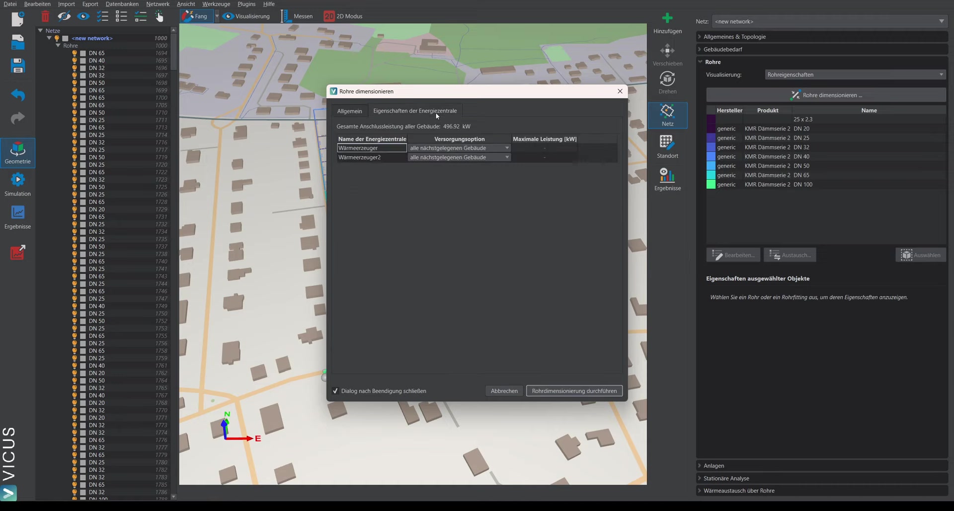
On the Energy plants tab, various options are available:
-
Supply all closest buildings (on both energy plants): The buildings are automatically split — it is determined which building is closer to which energy plant, and the pipe sizing is carried out accordingly.
-
Limit power: At the second heat generator, the power can be limited (e.g. to 200 kW). The first heat generator (with the “all closest buildings” option) then supplies the remaining buildings that cannot be covered with the 200 kW.
Performing the sizing ▶ 2:55
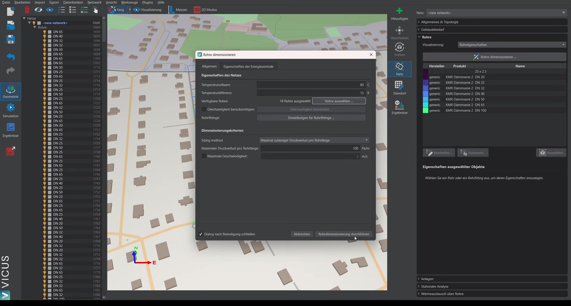
After performing the pipe sizing, the pipe sizes make it clear from which side which consumers are supplied. Simulation with multiple energy plants is covered in the next video.